
Liquid discharge head and recording device using same

A liquid ejection head, liquid technology, applied in the direction of inking device, printing, etc., can solve problems such as differences in displacement characteristics, and achieve the effect of reducing crosstalk

Inactive Publication Date: 2012-11-28
KYOCERA CORP
View PDF7 Cites 10 Cited by
  • Summary
  • Abstract
  • Description
  • Claims
  • Application Information

AI Technical Summary

Problems solved by technology

Due to this crosstalk, there is a problem in that the displacement characteristics of the displacement elements differ between the case where the adjacent displacement element is not driven and the case where it is driven.

Method used


Image

  • Liquid discharge head and recording device using same
  • Liquid discharge head and recording device using same
  • Liquid discharge head and recording device using same

Examples


Embodiment Construction

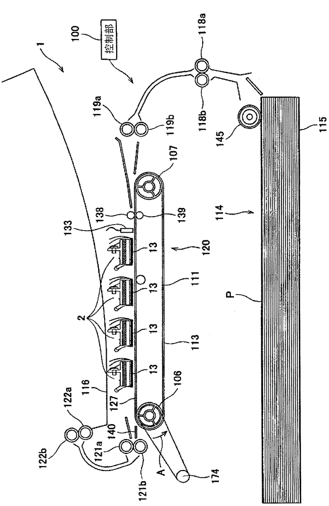
[0028] figure 1 It is a schematic configuration diagram showing an example of a recording device, that is, a color inkjet printer. This color inkjet printer 1 (hereinafter referred to as printer 1 ) has four liquid ejection heads 2 . These liquid ejection heads 2 are arranged along the conveyance direction of recording paper P as a recording medium, and are fixed to the printer 1 . The liquid ejection head 2 along the figure 1 The front has an elongated shape toward the depth direction.

[0029] In the printer 1 , along the conveyance path of the recording paper P, a paper feed unit 114 , a conveyance unit 120 , and a paper holder 116 are provided in this order. Further, the printer 1 is provided with a control unit 100 for controlling the operation of each unit of the printer 1 such as the liquid ejection head 2 and the paper feed unit 114 .

[0030] The paper feed unit 114 has a paper storage cassette 115 capable of storing a plurality of sheets of recording paper P, and...


PUM


Abstract

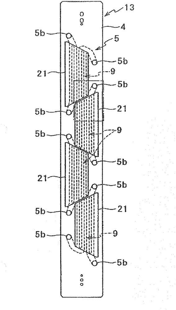
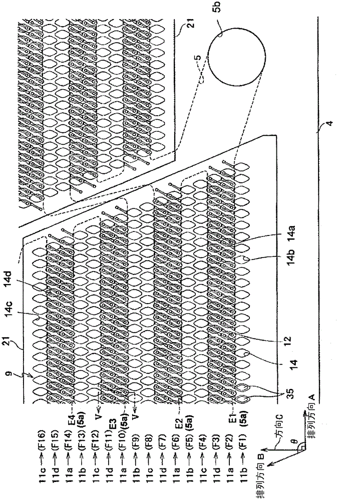
Provided are a liquid discharge head having reduced crosstalk between adjacent displacement elements, and a recording device using the liquid discharge head. A liquid discharge head formed by stacking on each other a flat plate-shaped flow path member and a flat plate-shaped piezoelectric actuator, the flat plate-shaped flow path member being provided with: liquid pressurizing chambers which are open in the main surface, arranged in a matrix pattern, and have the same shape; liquid discharge holes; and individual supply paths, the flat plate-shaped piezoelectric actuator being formed by stacking on a vibration plate a common electrode, a piezoelectric element layer, and individual electrodes, the vibration plate and the piezoelectric element layer being stacked so as to cover the liquid pressurizing chambers. In a plan view of the liquid discharge head, the opening of each liquid pressurizing chamber has a polygonal shape having at least one acute-angled corner, and the liquid pressurizing chamber and a connection electrode of each individual electrode, said connection electrode being led out to the outside of the liquid pressurizing chamber, are disposed within a parallelogram-shaped region including two sides which form the acute-angled corner of the liquid pressurizing chamber and also including two corners which are adjacent to the acute-angled corner.

Description

technical field [0001] The present invention relates to a liquid ejection head such as an inkjet recording head, and a recording device using the liquid ejection head. Background technique [0002] In recent years, printing devices using the inkjet recording method such as inkjet printers and inkjet plotters are not printers for general consumers, but are widely used in, for example, the formation of circuits or color filters for liquid crystal displays. In industrial applications such as manufacturing and manufacturing of organic EL displays. [0003] A liquid ejection head for ejecting liquid is mounted on such an inkjet printing device as a printing head. In this type of printing head, a thermal method and a piezoelectric method are generally known. In the thermal method, a heater is provided as a pressurizing mechanism in an ink flow path filled with ink, and the ink is heated by the heater. It is boiled, and the ink is pressurized by the bubbles generated in the ink f...

Claims


Application Information

Patent Timeline
Patent Type & Authority Applications(China)
IPC IPC(8): B41J2/045B41J2/055
CPCB41J2002/14306B41J2202/11B41J2002/14459B41J2002/14225B41J2002/14217B41J2202/20B41J2/14209B41J2002/14491
Inventor 松元步池内涉
Owner KYOCERA CORP
Learn More