Industrial vehicle control device

A technology for a control device and a working vehicle, which is applied to the control device, vehicle components, construction vehicles, etc., can solve problems such as improving fuel consumption, and achieve the effect of improving fuel consumption.

Active Publication Date: 2015-03-18
NIHON KENKI CO LTD
View PDF8 Cites 0 Cited by
  • Summary
  • Abstract
  • Description
  • Claims
  • Application Information

AI Technical Summary

Problems solved by technology

[0004] However, since work vehicles such as wheel loaders perform work while driving, it is difficult to use the method of driving to improve fuel consumption by dividing the actual fuel consumption obtained by dividing the fuel consumption by the distance traveled as a reference. Improve fuel consumption

Method used


Image

  • Industrial vehicle control device
  • Industrial vehicle control device
  • Industrial vehicle control device

Examples


no. 1 Embodiment approach

[0021] Below, refer to Figure 1-Figure 9 A control device for a work vehicle according to a first embodiment of the present invention will be described.

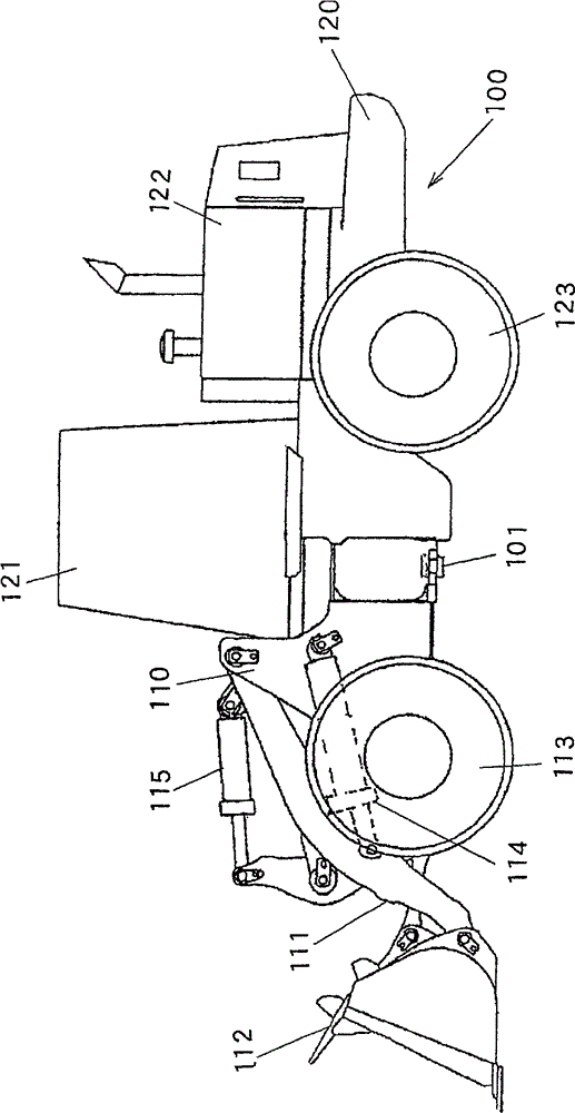
[0022] figure 1 It is a side view of a wheel loader as an example of a work vehicle to which the control device according to the present embodiment is applied. The wheel loader 100 is composed of a front body 110 having an arm 111 , a bucket 112 , tires 113 and the like, and a rear body 120 having a cab 121 , an engine compartment 122 , tires 123 and the like. The arm 111 is rotated vertically (pitch motion) by the drive of the arm cylinder 114 , and the bucket 112 is rotated vertically (dumping or scooping) by the drive of the bucket cylinder 115 . The front body 110 and the rear body 120 are rotatably connected to each other by a center pin 101 , and the front body 110 is bent left and right relative to the rear body 120 by expansion and contraction of a steering cylinder (not shown).

[0023] figure 2 It is a figure...

no. 2 Embodiment approach

[0052] A control device for a work vehicle according to a second embodiment will be described. The work vehicle control device of the second embodiment differs from the work vehicle control device of the first embodiment only in the processing in the controller 10 . Since other configurations are the same as those of the first embodiment, description thereof will be omitted, and the processing of the controller 10 will be described below.

[0053] Figure 10 It is a flowchart showing processing in the controller 10 in the second embodiment. Figure 10 with the first embodiment Figure 9 Corresponding. For the same as the first embodiment Figure 9 The same process is labeled with the same step number.

[0054] The processing shown in this flowchart starts, for example, from activation of the engine key switch, similarly to the first embodiment. In step S1, signals from various detectors 12-15 and switches 7-9 are read. In step S21, it is determined whether or not the to...


PUM


Abstract

A work vehicle control device includes: a rotation speed control unit that controls a rotation speed of an engine in correspondence to an accelerator pedal operation quantity indicating an extent to which an accelerator pedal is operated; a speed ratio detection unit that detects a speed ratio of a speed at an input shaft and a speed at an output shaft of a torque converter, which is disposed between the engine and wheels to transmit rotation of the engine to the wheels; a decision-making unit that makes a decision that a fuel efficiency deteriorating condition exists if the torque converter speed ratio detected via the speed ratio detection unit is less than a predetermined value or if the torque converter speed ratio detected via the speed ratio detection unit is equal to or greater than the predetermined value and a target engine rotation speed corresponding to an operation of the accelerator pedal is greater than a preset value; and an informing unit that informs results of the decision made by the decision-making unit.

Description

technical field [0001] The present invention relates to a control device for a work vehicle such as a wheel loader equipped with a torque converter. Background technique [0002] There is known a device capable of urging an operator to drive to improve fuel efficiency during vehicle driving (for example, refer to Patent Document 1). In the device described in this Patent Document 1, the actual fuel consumption is compared with a preset target value, and an alarm is issued when it is determined that the actual fuel consumption is greater than the target value. The actual fuel consumption is calculated by dividing the fuel consumption by the distance traveled. [0003] Patent Document 1: Japanese Patent Application Laid-Open No. 4-366729 [0004] However, since work vehicles such as wheel loaders perform work while driving, it is difficult to use the method of driving to improve fuel consumption by dividing the actual fuel consumption obtained by dividing the fuel consumptio...

Claims


Application Information

Patent Timeline
IPC IPC(8): B60R16/02B60K35/00
CPCB60W2540/10B60K2350/1092B60Y2200/415B60W2300/17B60W2510/0241B60W2510/0638B60W30/1882Y02T10/84B60K35/28B60K2360/174B60W10/06B60W10/10B60W40/105B60W50/14
Inventor 兵藤幸次吉川正规高桥咏原克太
Owner NIHON KENKI CO LTD
Why Eureka
Try Eureka