Valve driving device for internal combustion engine

A technology of valve drive and internal combustion engine, which is applied in the direction of valve device, machine/engine, engine lubrication, etc. It can solve the problems of lower output efficiency of internal combustion engine, high friction and wear, and large metal noise, etc., and achieve miniaturization and weight reduction , Noise reduction effect

Inactive Publication Date: 2007-04-25
MITSUBISHI MOTORS CORP
View PDF4 Cites 0 Cited by
  • Summary
  • Abstract
  • Description
  • Claims
  • Application Information

AI Technical Summary

Problems solved by technology

[0015] Therefore, when the lift amount is the largest, the attitude of the valve lifter 904 changes to a large range, and at the same time, when the valve lifter 904 hits the inner surface of the guide hole 903, the oil film at the gap is pushed to one side, thereby generating a large Metallic noise, further, due to greater friction and wear, may reduce the output efficiency and fuel consumption of the internal combustion engine

Method used


Image

  • Valve driving device for internal combustion engine
  • Valve driving device for internal combustion engine
  • Valve driving device for internal combustion engine

Examples


Embodiment Construction

[0059] Now, a more detailed description of a preferred embodiment of the present invention will be given with reference to the accompanying drawings.

[0060] A valve driving device according to a first embodiment of the present invention will be described with reference to FIGS. 1 to 3 .

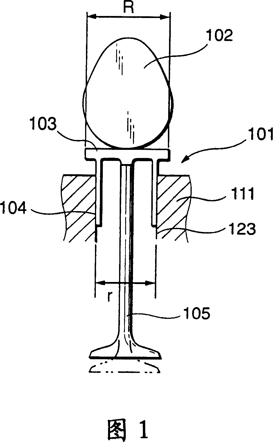
[0061] 1, the valve lifter 101 includes a lifter portion 103 in contact with a cam 102 provided on a cylinder head 111 of an internal combustion engine, and a portion of the lifter portion 103 in contact with the protruding portion of the cam 102 is made substantially Flat disc shape, the protruding part of the cam 102 is in line contact with the tappet part 103, the valve lifter 101 includes a hollow cylindrical guide part 104 continuous to the lower part of the tappet part 103, the guide part 104 is slidably placed on In the guide hole 123 of the cylinder head 111 , the diameter r of the guide portion 104 is set to be smaller than the diameter R of the tappet portion 103 .

[0062] Using...


PUM


Abstract

This invention relates to a valve driving apparatus using a direct driving type valve lifter which is disposed between a cam formed at a cam shaft and a poppet valve which is provided in a path formed at the cylinder head of an internal combustion engine and moves to the axial direction of the valve to open and close the path, comprising a guide hole formed at the cylinder head; and a direct driving type valve lifter having a tappet portion which is brought in contact with the cam and pressed by the cam, and a guide portion having one end portion coupled to the tappet portion and housed within the guide hole so as to slide freely therein to the axial direction of the poppet valve in an interlocked manner as a pushing operation of the tappet portion by the cam, wherein the diameter of the guide portion (104) is formed to be smaller than the diameter of the tappet portion.

Description

[0001] This case is a divisional application of the Chinese patent application number: 00109043.7, the application date is June 7, 2000, and the invention name is "valve driving device for internal combustion engine". technical field [0002] The present invention relates to a valve driving device for driving a valve which opens and closes an intake port or an exhaust port in an internal combustion engine, and more particularly, the present invention relates to a valve driving device using a direct drive type valve lifter, Use of the lifter enables miniaturization and weight reduction of the valve while protecting a sufficient lift amount to improve its working efficiency. Background technique [0003] A valve driving device using a poppet of a direct drive type valve has been disclosed, for example, in Japanese Unexamined Patent Publication No. Hei 10-331709. A direct drive type valve lifter comprising a lifter portion in contact with a cam provided on the cylinder head of ...

Claims


Application Information

Patent Timeline
Patent Type & Authority Patents(China)
IPC IPC(8): F01L1/14F01L1/00F01M9/10
CPCF01L2810/02F01L1/14F01M9/104F01M9/10F01L1/143F01L1/00
Inventor 村田真一东博文宫本秀树
Owner MITSUBISHI MOTORS CORP
Why Eureka
Try Eureka