Radiating antenna element

A radiation unit and antenna radiation technology, which is applied in antennas, antenna unit combinations with different polarization directions, antenna coupling, etc., to achieve the effects of improving radio performance, improving directivity, and improving multi-band operation capabilities

Inactive Publication Date: 2012-11-28
ALCATEL LUCENT SAS
View PDF7 Cites 22 Cited by
  • Summary
  • Abstract
  • Description
  • Claims
  • Application Information

AI Technical Summary

Problems solved by technology

[0005] However, the emergence of new services (multimedia, 4G telephony, 2-66GHz broadband mobile access systems), which require multi-polar operation in high frequency bands and in very compact environments, makes existing radiating units present

Method used


Image

  • Radiating antenna element
  • Radiating antenna element
  • Radiating antenna element

Examples


Embodiment Construction

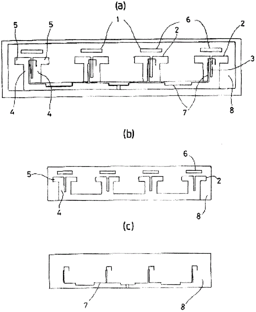
[0043] figure 1 a to figure 1c depicts an embodiment of a planar rectilinear arrangement of vertically polarized radiation elements 1 . The radiating element 1 contains a half-wave dipole 2 consisting of two half-dipoles separated by a slot 3, each half-dipole comprising a base 4 supporting an arm 5. The two arms 5 of the dipole 2 define radiation lines. To increase gain and bandwidth, another radiation line is added on top of this radiation line, which is formed by parasitic or "director" elements 6 that are not electrically connected to the dipoles 2 . The dipole 2 is fed by a wire 7 connected to a balun, which is not shown in the figure. The strip dipole 2 and parasitic element 6 are printed with low dielectric constant ε rr (1rr figure 1 b), the substrate is, for example, a Teflon and glass plate from the company "TACONIC" with the product code "TLX-08". The wires 7 are printed on the reverse side of the dielectric substrate 8 ( figure 1 c).

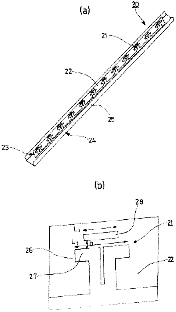
[0044] figure 2 a an...


PUM


Abstract

The present invention relates to an antenna (array) including at least one radiating element (1). The radiating element (1) includes at least one dipole (2, 124), comprising a foot (4) and arms (5), printed on one of the surfaces of a mounting (substrate, 8, 122) with a high dielectric constant. The dipole (2, 124) is powered by at least one conductive line (7), printed on the substrate (8, 122). At least one static element (director, 6, 125) is also printed on the substrate (8, 122) of the dipole (2, 124) and arranged parallel to the arms (5) of the dipole (2, 124). At least one other additional static element (120) is arranged in a horizontal plane (121) perpendicular to the plane of the substrate (8, 122) supporting the radiating element (1) and parallel to the arms (5) of the dipole (2, 124) of the radiating element. The additional static element (120) is inserted between the rows of radiating elements (1).

Description

technical field [0001] The present invention relates to the field of transmission of radio waves using communication antennas in the ultra-high frequency domain using radiating elements. Background technique [0002] Radiating units of various shapes have been developed for mobile communication services such as GSM, DCS / PCS, UMTS, and the like. In particular, one of these is a radiating element called a "butterfly" element, wherein the element is formed by two dipoles intersecting each other with orthogonal polarizations of 45°. These units present various advantages in terms of wireless performance, industrialization capability, production cost, and robustness. This is why these units are heavily used in sub-2.5GHz applications. For the high frequency band, the size and installation method of the radiating unit are very limited, so this type of unit has certain limitations due to its size and mechanical properties. [0003] This is why, for example, for WIMAX antennas (b...

Claims


Application Information

Patent Timeline
IPC IPC(8): H01Q1/52H01Q9/28H01Q19/24H01Q21/06H01Q21/08H01Q21/26H01Q1/24
CPCH01Q21/08H01Q1/523H01Q19/24H01Q19/005H01Q21/062H01Q9/285H01Q21/26
Inventor S·谢农J-P·阿雷尔A·伊拉里
Owner ALCATEL LUCENT SAS
Why Eureka
Try Eureka