Ultrasonic postpositional unidirectional vibration turning method

A vibratory turning and ultrasonic technology, which is applied in the direction of fluid using vibration, can solve the problems of no vibration, failure, and unstable output of ultrasonic energy, and achieve the effect of guaranteed effect and stable vibration

Inactive Publication Date: 2012-12-05
赵显华
View PDF10 Cites 6 Cited by
  • Summary
  • Abstract
  • Description
  • Claims
  • Application Information

AI Technical Summary

Problems solved by technology

[0006] The above existing ultrasonic vibration turning methods all fixedly connect the horn and the turning tool bar (or turning tool) as a whole. The problem with this method is that when the turning parameters (such as linear speed, cutting depth, When the amount of feeding, etc.) changes, the load characteristics of turning will change, and the change of this load will directly affect the stability of ultrasonic energy output, and the instability o

Method used


Image

  • Ultrasonic postpositional unidirectional vibration turning method
  • Ultrasonic postpositional unidirectional vibration turning method
  • Ultrasonic postpositional unidirectional vibration turning method

Examples


Example Embodiment

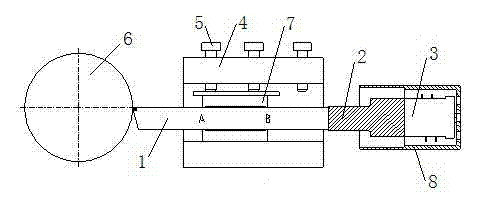
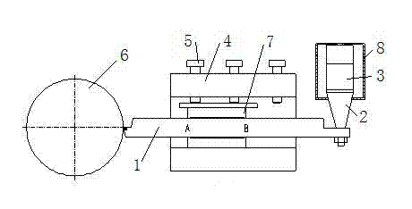
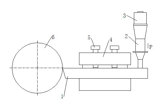
[0019] like image 3 Shown, the ultrasonic vibration turning method of the present invention and figure 1 and figure 2 The difference in the existing ultrasonic vibration turning technology given is that the horn and the cutter bar (or turning tool) were tightly connected in the past, but in the present invention, the horn 2 is pushed against the protruding installation of the turning tool. The rear portion other than the tool holder of the turning tool, the horn 2 is not fixedly connected with the turning tool 1, but only in contact. The horn 2 is connected to the transducer 3 to electrically connect the transducer to an external ultrasonic generator. During the turning process, a pressure is applied to the horn 2, and the pressure is applied to the horn 2. The pressure can be applied by a spring, a hydraulic mechanism or a pneumatic mechanism. The pressure acts on the tool bar of the turning tool 1 through the horn 2, so that there is always a pressure between the horn 2...


PUM


Abstract

The invention relates to an ultrasonic postpositional unidirectional vibration turning method. One end of an amplitude transformer acts on a toolbar of a turning tool; the part of the turning tool, on which the amplitude transformer acts, is the rear part of the turning tool extending out of a tool rest for mounting the turning tool; the amplitude transformer is not connected with the toolbar of the turning tool in a fastening manner but is in contact with the toolbar of the turning tool; the other end of the amplitude transformer is connected with a transducer which is electrically connected with an ultrasonic generator; when pressure is applied on the amplitude transformer, the pressure ensures that the amplitude transformer is in contact with the toolbar of the turning tool all the time throughout the turning process; when the ultrasonic generator is switched on, the transducer converts an electric oscillation signal into ultrasonic frequency mechanical vibration; the amplitude transformer amplifies and transmits the ultrasonic frequency mechanical vibration of the transducer to the turning tool; turning parameters have no direct effect on the stable output of ultrasonic energy no matter how the turning parameters vary; the stable output of the ultrasonic energy allows the toolbar of the turning tool to obtain a stable vibration force; and the vibration stabilization of a turning tool nose is ensured, thereby ensuring the effects of ultrasonic vibration turning.

Description

technical field [0001] The invention relates to a method for performing ultrasonic turning on a workpiece on a lathe, and belongs to the technical field of ultrasonic turning. Background technique [0002] Ultrasonic vibration turning refers to the turning of the turning tool along the cutting direction at the vibration frequency and small amplitude of the ultrasonic range of vibration frequency f=16-50KHz and amplitude a=10-25μm. Utilizing this kind of vibration cutting, ultra-precision machining can be realized on ordinary lathes, that is, roundness, cylindricity, flatness, parallelism, and straightness can all be close to zero error, and lathes can be used instead of grinding. The application of ultrasonic turning has the following advantages: 1. Reduced cutting force: Vibratory turning is a kind of pulse cutting from a microscopic point of view. The effective cutting time of the tool in one vibration cycle is extremely short, and most of the time in one vibration cycle. ...

Claims


Application Information

Patent Timeline
IPC IPC(8): B23B1/00B06B1/02
Inventor 赵显华
Owner 赵显华
Why Eureka
Try Eureka