


Quick Research
Generate reliable direction feasibility study reports for your R&D in just a few steps.

Technical Q&A
Discover and master advanced knowledge NOW. Basics, ideas, possibilities, all at once.

Find Solutions
As an expert in R&D theories, this can generate solutions to your technical problems instantly.

Evaluate Feasibility
Analyze your overall solution with one click, know your potential R&D risks in advance.

Monitor Landscape
Get weekly tech updates, stay abreast of the latest tech innovations and key insights.
New reactor flowscheme for dehydrogenation of propane to propylene
A dehydrogenation reactor, a technology for propane dehydrogenation, which is applied in the field of propane dehydrogenation and can solve problems such as catalyst deactivation
- Summary
- Abstract
- Description
- Claims
- Application Information
AI Technical Summary
Problems solved by technology
Method used
Image

Examples
Embodiment Construction
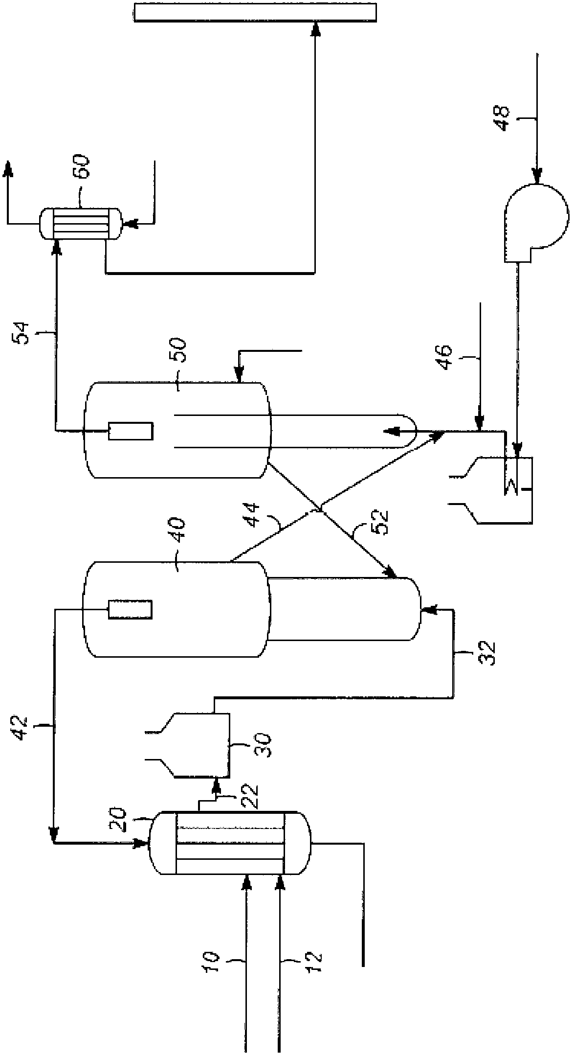
[0010] Dehydrogenation of hydrocarbons is important for the production of olefins. Olefins are important for a variety of products such as polymer plastics, or the use of olefins in the formation of alkylaryl compounds. A method for propane dehydrogenation is presented. The process includes passing a preheated propane feed stream into a dehydrogenation reactor. The feed stream is contacted with the fluidized catalyst in a dehydrogenation reactor, thereby producing a product stream comprising propylene. The reactor is a fast fluidized reactor, where the reactor is operated in flow mode to turbulently mix the catalyst and feed streams. The catalyst and product streams are passed upwardly through the reactor and separated in a separation section whereby a product stream comprising propylene exits the reactor. The spent catalyst is passed into a catalyst regeneration unit to regenerate the catalyst for return to the dehydrogenation reactor.
[0011] The fast fluidized reactor ...
PUM
 Abstract
Description
Claims
Application Information
 - R&D Engineer
- R&D Manager
- IP Professional
- Industry Leading Data Capabilities
- Powerful AI technology
- Patent DNA Extraction
Browse by: Latest US Patents, China's latest patents, Technical Efficacy Thesaurus, Application Domain, Technology Topic, Popular Technical Reports.
© 2024 PatSnap. All rights reserved.Legal|Privacy policy|Modern Slavery Act Transparency Statement|Sitemap|About US| Contact US: help@patsnap.com