
Rankine cycle system

A circulatory system, Rankine's technology, applied in the field of Rankine circulatory system, can solve the problem of high cost and achieve the effect of inhibiting deterioration and damage

Inactive Publication Date: 2012-12-05
TOYOTA JIDOSHA KK
View PDF5 Cites 10 Cited by
  • Summary
  • Abstract
  • Description
  • Claims
  • Application Information

AI Technical Summary

Problems solved by technology

However, in order to realize these controls, an actuator for operating the control valve, a temperature sensor for setting the control timing, or a logic structure for estimating the temperature are required, which increases the cost.

Method used


Image

  • Rankine cycle system
  • Rankine cycle system
  • Rankine cycle system

Examples


Embodiment

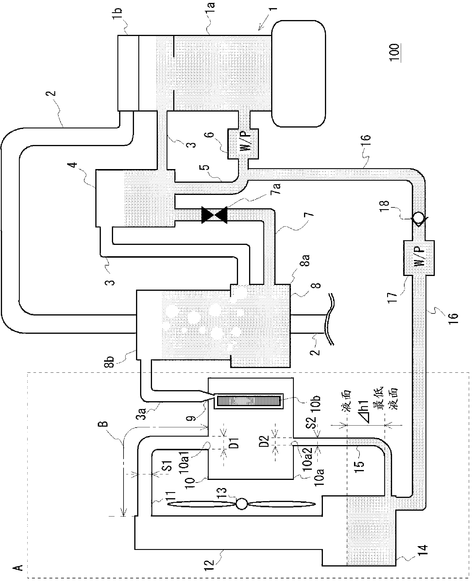
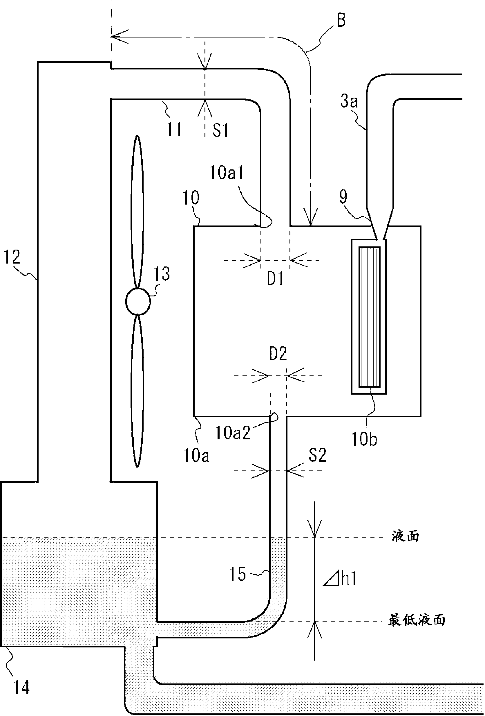
[0020] refer to figure 1 , figure 2 A brief configuration of the Rankine cycle system 100 will be described. figure 1 It is a schematic configuration diagram of the Rankine cycle system 100 . figure 2 is zoomed in figure 1 Explanatory diagram of part A in. The Rankine cycle system 100 includes the engine 1 cooled by boiling the refrigerant inside. The engine 1 is an example of an internal combustion engine corresponding to a steam generator. The engine 1 includes a cylinder block 1a and a cylinder head 1b. A water jacket is formed in the cylinder block 1a and the cylinder head 1b, and the engine 1 is cooled by boiling the refrigerant in the water jacket. At this time, the engine 1 generates steam. The engine 1 further includes an exhaust pipe 2 . A cylinder head 1 b of the engine 1 is connected to one end of a steam passage 3 .

[0021] A gas-liquid separator 4 is arranged in the steam passage 3 . The refrigerant flowing into the gas-liquid separator 4 in a gas-liq...


PUM


Abstract

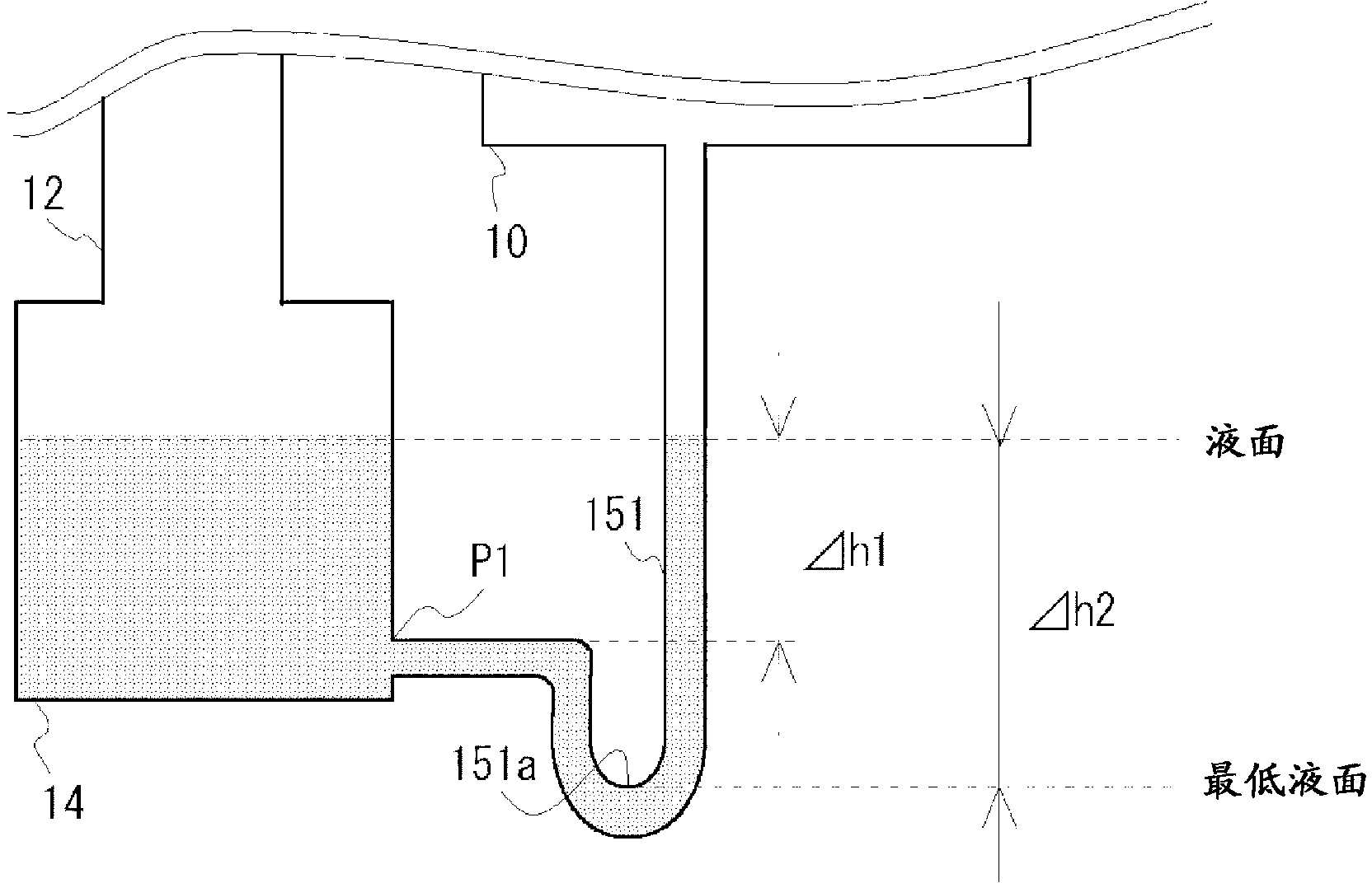
Disclosed is a Rankine cycle system (100) provided with a superheater (8) and an expander (10) which is driven by steam, i.e., vaporized refrigerant supplied from the expander (8), to recover energy. The expander (10) is provided with a first discharge port (10a1) for discharging steam and a second discharge port (10a2) for discharging vaporized refrigerant generated by condensing steam on the inside of the expander (10). The Rankine cycle system (100) is provided with a first discharge passage (11) which is connected to the first discharge port (10a1) and which discharges the steam from the expander (10), and a condenser (12) wherein the steam is introduced through the first discharge passage (11), and the introduced steam is condensed to produce liquefied refrigerant. The liquefied refrigerant generated in the condenser (12) is stored in a condensed water tank (14). The second discharge port (10a2) is connected to the condensed water tank (14) by a second discharge passage (15).

Description

technical field [0001] The present invention relates to a Rankine cycle system. Background technique [0002] Conventionally, there is known a Rankine cycle for recovering useless heat generated during the operation of an internal combustion engine. In such a Rankine cycle, for example, the water cooling system of the engine is set in a closed structure to perform boiling cooling, and the expander of the steam turbine is driven by the refrigerant vaporized by the useless heat in the engine, that is, steam, and the steam The existing thermal energy is converted into electrical energy for recovery. There is Patent Document 1, for example, of improving such a Rankine cycle system. [0003] Patent Document 1: Japanese Patent Laid-Open No. 2009-103060 [0004] However, in the proposal of the above-mentioned Patent Document 1, for example, at the time of cold start of the internal combustion engine, the following disadvantages may occur. When the internal combustion engine is ...

Claims


Application Information

Patent Timeline
IPC IPC(8): F01K9/00F01D25/32
CPCF01K23/065F01K25/10F01K9/00
Inventor 山田贤一小林日出夫石川雅英杉山敏久
Owner TOYOTA JIDOSHA KK
Learn More