Eureka AIR delivers breakthrough ideas for toughest innovation challenges, trusted by R&D personnel around the world.

Power chassis of double crawler belt-type micro tillage machine

A power chassis and crawler-type technology, which is applied in the field of field micro-cultivation management machines, can solve the problems of easy deformation of the gearbox, large traction resistance of equipment, and difficult operation, so as to improve operation stability, reduce operation difficulty, and strong climbing ability Effect

Inactive Publication Date: 2012-12-12
HENAN UNIV OF SCI & TECH
View PDF11 Cites 10 Cited by
  • Summary
  • Abstract
  • Description
  • Claims
  • Application Information

AI Technical Summary

Problems solved by technology

The wheel-type walking mechanism has the disadvantages of high slip rate and poor passing performance, and most of the existing micro-tillers use cast iron gearboxes as the power chassis of the machine, that is, the installation position of the rotary tillage working parts and the walking distance are directly arranged on the gearbox. The connection of the wheels has caused the problems of easy deformation of the gearbox, short machine life, single function of the tiller, and few working parts for expandable connections.
In addition, there are a few models that use a single track as the walking mechanism. Due to the reaction force of the soil on the rotary tiller, the lateral stability of the machine is poor, and the operator relies on physical strength to maintain the balance of the machine body, making it difficult to operate.
Due to the lack of a formed micro-tiller power chassis, the power matching performance between the agricultural machinery and the micro-tiller is poor, and there are often phenomena such as insufficient power and large traction resistance of the machine.

Method used


Image

  • Power chassis of double crawler belt-type micro tillage machine
  • Power chassis of double crawler belt-type micro tillage machine
  • Power chassis of double crawler belt-type micro tillage machine

Examples


Embodiment Construction

[0019] The present invention can be explained in more detail by referring to the accompanying drawings and the following embodiments, and the present invention is not limited to the combination of the following embodiments.

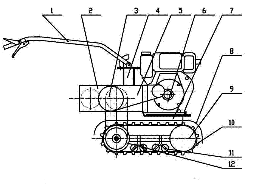
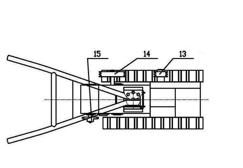
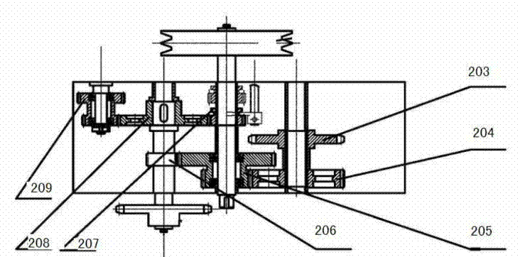
[0020] As shown in the figure, a power chassis of a double-crawler micro-cultivator includes an engine 6 and a frame 7. On the frame 7, an armrest 1 and an armrest platform 4 are also provided, and a belt transmission mechanism 5, a gearbox 2, The chain transmission mechanism 3 and the crawler belt running mechanism arranged at the bottom of the frame 7, the power output of the engine 6 is transmitted to the gearbox 2 through the belt transmission mechanism, and the power is divided into two outputs after the gearbox 2 changes speed, and the power output of one path is to The crawler belt drive wheel in the crawler belt traveling mechanism drives the whole chassis to walk, and another part of the power is sent to the chain transmission mechanism 3, and dri...


PUM


Abstract

The invention discloses a power chassis of a double crawler belt-type micro tillage machine. The power chassis comprises an engine, a rack, a belt transmission mechanism, a speed changing box, a chain transmission mechanism, and a crawler belt traveling mechanism arranged at the bottom of the rack, wherein power output by the engine is output to the speed changing box through the belt transmission mechanism; after speed change of the speed changing box, the power is output in two ways; one way of power is output to a crawler belt driving wheel in the crawler belt traveling mechanism to drive the whole chassis to travel; and other way of power is output to the chain transmission mechanism to drive external working parts by a chain drive driving wheel. With the adoption of the device, the operation stability of the micro tillage machine is improved, and the manipulation difficulty of a machinist is lightened; and the power chassis of the double crawler belt-type micro tillage machine also has the advantages of strong climbing ability, flexibility in steering, large tractive force and small slipping rate.

Description

technical field [0001] The invention relates to a field micro cultivator management machine, in particular to a power chassis of a double crawler micro cultivator. Background technique [0002] Tillers currently on the market generally use wheeled walking mechanisms, which are divided into two categories: 1. Tires are used during transportation, and tires are removed and replaced with working parts such as rotary blades or weeding wheels during work; 2. Front wheels are used The structure of the knife or the front knife and the rear wheel. The wheel-type walking mechanism has the disadvantages of high slip rate and poor passing performance, and most of the existing micro-tillers use cast iron gearboxes as the power chassis of the machine, that is, the installation position of the rotary tillage working parts and the walking distance are directly arranged on the gearbox. The connection of the wheels has caused the problems of easy deformation of the gearbox, short machine li...

Claims


Application Information

Patent Timeline
Patent Type & Authority Applications(China)
IPC IPC(8): A01B33/08A01B51/02
Inventor 姬江涛杜新武贺智涛杜蒙蒙郑治华何亚凯刘剑君马俊伟
Owner HENAN UNIV OF SCI & TECH
Why Eureka
Eureka Blog
Learn More