Mechanical arm high-angle controllable rotary joint device driven by two steel wire ropes

A technology of steel wire rope and mechanical arm, applied in the field of large-angle controllable rotary joint device of the mechanical arm, to achieve the effect of high transmission efficiency and low friction loss

Inactive Publication Date: 2012-12-12
HEFEI INSTITUTES OF PHYSICAL SCIENCE - CHINESE ACAD OF SCI
View PDF7 Cites 25 Cited by
  • Summary
  • Abstract
  • Description
  • Claims
  • Application Information

AI Technical Summary

Problems solved by technology

[0006] The purpose of the present invention is to provide a large-angle controllable rotary joint device of a mechanical arm driven by double wire ropes, so as to solve the slippage problem between the wire rope a

Method used


Image

  • Mechanical arm high-angle controllable rotary joint device driven by two steel wire ropes
  • Mechanical arm high-angle controllable rotary joint device driven by two steel wire ropes
  • Mechanical arm high-angle controllable rotary joint device driven by two steel wire ropes

Examples


Embodiment 1

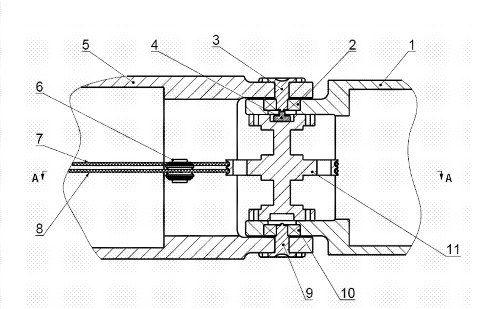
[0031] figure 1 A cross-sectional schematic diagram of the overall structure of the large-angle controllable rotary joint device of the mechanical arm driven by double wire ropes of the present invention is given. Such as figure 1 As shown in , the large-angle controllable rotary joint device of the mechanical arm driven by double wire ropes in this embodiment includes: the front-stage mechanical arm 1, the first bearing 2, the first rotating shaft 3, the angle sensor 4, the rear-stage mechanical arm 5, and the steel wire rope Pretensioning device 6, left-handed steel wire rope 7, right-handed steel wire rope 8, second rotating shaft 9, second bearing 10, steel wire roulette 11.

[0032] The non-output shaft end of the angle sensor 4 is placed at the bottom of the cavity of the flange at the upper end of the rotating shaft of the wire roulette 11, and the output shaft of the angle sensor 4 is adjusted to maintain a coaxial relationship with the rotating shaft of the wire roul...


PUM


Abstract

The invention discloses a mechanical arm high-angle controllable rotary joint device driven by two steel wire ropes. The mechanical arm high-angle controllable rotary joint device is characterized in that a front-stage mechanical arm and a rear-stage mechanical arm are connected through a rotation shaft and a bearing and rotate relative to each other; a steel wire wheel disc is fixed between an upper boss and a lower boss of the front-stage mechanical arm; a shaft of an angle sensing output device which is arranged in a cavity in the middle of a flange at one end of a rotation shaft of the steel wire wheel disc is coaxial with the rotation shaft and rotates synchronously with the rotation shaft; two driving steel wire ropes are clamped on groove through holes through ball heads and are wound in a U-shaped groove of the rim of the steel wire wheel disc; and a steel wire rope pre-tightening device is used for adjusting pre-tightening force of the driving steel wire ropes through adjustment screws. According to the joint device provided by the invention, the joint displacement can be obtained in real time so that the accurate control of joints is realized; and the relative sliding does not occur between each steel wire rope and the steel wire wheel disc, so that the rolling contact is realized between each steel wire rope and the steel wire rope pre-tightening device, the frictional loss is small, the steel wire rope transfer efficiency is high and the applicability is brought to the serial-connect expansion of the multi-stage mechanical arms.

Description

technical field [0001] The invention belongs to the technical field of mechanical arm joints, in particular to a large-angle controllable rotary joint device of a mechanical arm driven by double wire ropes. Background technique [0002] Existing robotic arms are usually composed of multi-stage joints connected in series, and are used as the supporting part of the end manipulator, and are mostly used for remote control, target detection and other multi-degree-of-freedom poses and obstacle avoidance applications. The controllable rotary joint structure of the manipulator is the key element that determines the positioning accuracy and spatial movement capability of the end of the manipulator. [0003] In the narrow and deep movement space, the obstacle avoidance ability of the manipulator is highly required. In order to reduce the self-weight of the multi-stage tandem manipulator and improve the carrying capacity of its end, the use of steel wire ropes for joint drive has been ...

Claims


Application Information

Patent Timeline
IPC IPC(8): B25J17/02
Inventor 吴宝元彦清泉张强汪增福
Owner HEFEI INSTITUTES OF PHYSICAL SCIENCE - CHINESE ACAD OF SCI
Why Eureka
Try Eureka