Electrically-driven high-speed turnout reversing device

A reversing device and electric drive technology, applied in the direction of transportation and packaging, conveyor objects, etc., can solve the problems of accelerating the speed of pushing blocks, equipment shutdown, long response time, etc., to reduce equipment use and maintenance costs, reduce roughness Degree requirements, the effect of improving safety and reliability

Active Publication Date: 2012-12-12
SHANGHAI DAMON LOGISTICS TECH
View PDF7 Cites 16 Cited by
  • Summary
  • Abstract
  • Description
  • Claims
  • Application Information

AI Technical Summary

Problems solved by technology

The defective that this switch reversing mechanism exists is:
[0007] 3) Due to the characteristics of the cylinder itself and the large linear motion stroke of the push fork, the frequency of the switch to complete the reversing is not high enough to meet the high-speed operation of the push block travel pin
[0008] 4) The stability and reliability of the reversing mechanism of the turnout is not high. When the push block travel pin travels at high speed in the guide groove, if the cylinder pushes the shift fork to do linear motion and is blocked, the push block travel pin and the shifting pin are prone to occur. The phenomenon of fork collision causes mechanical damage to the push block walking pin or shift fork, which eventually leads to equipment shutdown and production stop
[0009] 5) The shift fork is driven by the cylinder, and the cylinder needs to be additionally equipped with a solenoid valve to control the drive. In this way, the response time required for the shift fork drive needs to be superimposed by the solenoid valve and the cylinder. The response time is long, which is not conducive to accelerating the walking speed of the push block.

Method used


Image

  • Electrically-driven high-speed turnout reversing device
  • Electrically-driven high-speed turnout reversing device
  • Electrically-driven high-speed turnout reversing device

Examples


Embodiment Construction

[0025] The present invention will be further described below in conjunction with specific examples.

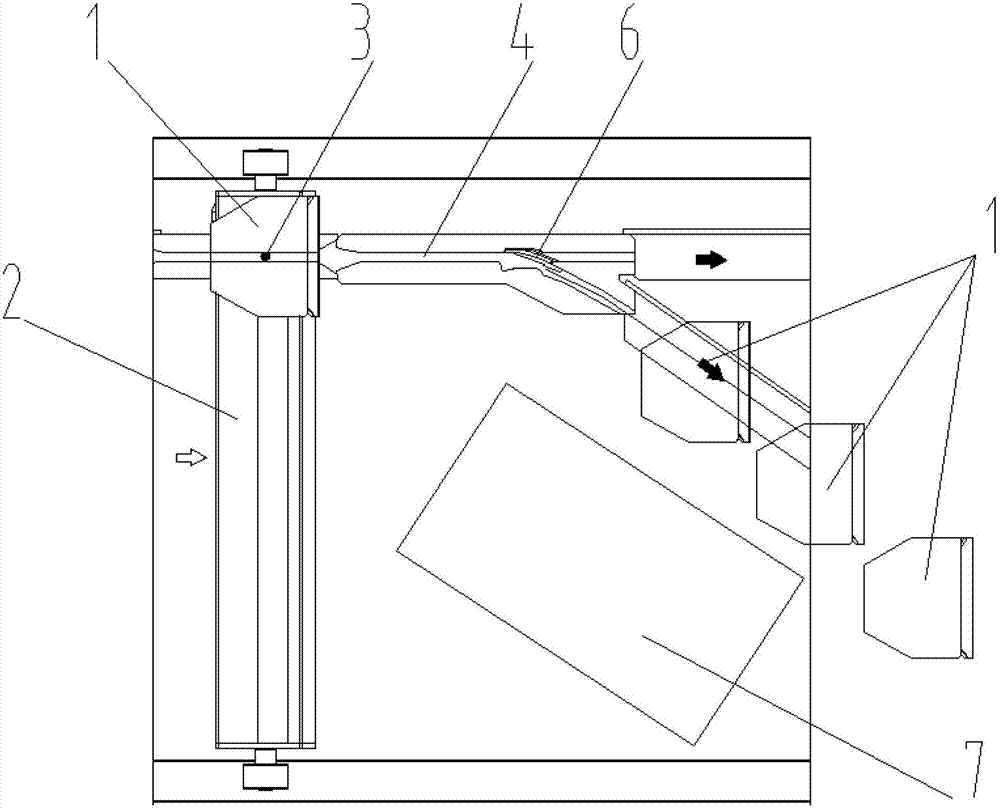
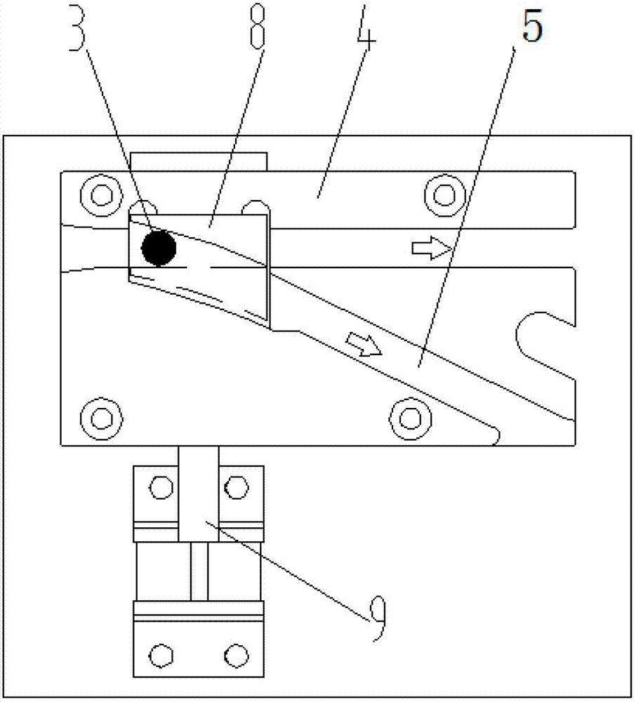
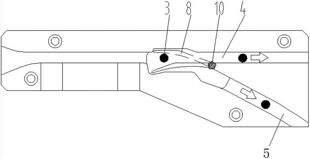
[0026] like figure 1 , image 3 As shown, an electrically driven high-speed turnout reversing device includes: a traveling mechanism 2, the traveling mechanism 2 is in the shape of a horizontal rod, and a roller perpendicular to the rod is provided at both ends of the rod, and the two rollers are arranged on a pair of parallel tracks. Rolling inside, the rod is covered with a push block 1, the push block 1 can slide along the rod, a push block travel pin 3 is provided at the bottom of the push block 1; a travel pin guide rail, the guide rail is located below the push block 1 and Perpendicular to the traveling mechanism 2, parallel and connected with the guide groove 4, the traveling pin 3 can enter the guide groove 4 at the same time; the switch reversing mechanism 6, the switch reversing mechanism 6 includes a switch base, and the switch base is provided with There is a shi...


PUM


Abstract

The invention relates to a slider type sorting machine, particularly relates to an electrically-driven high-speed turnout reversing device for the slider type sorting machine, and belongs to the technical field of logistics equipment. The electrically-driven high-speed turnout reversing device is characterized in that one end of a strip shifting fork is fixed to a cross joint of two guide rails through a rotary shaft, the other end of the strip shifting fork can be electrically driven in arc movement along the rotary shaft to shift back and forth between two guide grooves, and an electromagnetic solenoid driving mode is adopted by a shifting fork driving device. By means of electrical driving, single-time shifting fork reversing action can be completed in 8ms which is much lower than air cylinder action time of 30ms. The strip shifting fork in arc movement along the rotary shaft instead of linear movement can greatly reduce operating amplitude, improve reversing efficiency and increase conveying speed; the requirement on roughness of the contact face of the shifting fork with a rail can be lowered, and safety reliability of equipment is greatly improved; and air source compression is not needed, and utilization cost and maintenance cost of the equipment can be reduced.

Description

technical field [0001] The invention relates to a slider type sorter, in particular to an electrically driven high-speed switch reversing device of the slider type sorter, belonging to the technical field of logistics equipment. Background technique [0002] In modern society, logistics transportation and sorting technology has long become an indispensable part of people's daily life. In order to speed up logistics, logistics transportation and logistics sorting can be carried out simultaneously. Items need to be sorted layer by layer during the transportation process. They were sent to their respective destinations respectively, so professional high-speed logistics sorting equipment appeared. [0003] like figure 1 As shown, it includes a traveling mechanism 2. There are rollers at both ends of the traveling mechanism 2, and it moves forward along the tracks on both sides under the action of an external force. The traveling mechanism is covered with a push block 1, and the...

Claims


Application Information

Patent Timeline
Patent Type & Authority Applications(China)
IPC IPC(8): B65G47/52
Inventor 白振成耿晨宇马贤祥
Owner SHANGHAI DAMON LOGISTICS TECH
Why Eureka
Try Eureka