Underground repetitive shock irritation device and shock irritation method for oil and gas well drilling

A technology of oil and gas drilling and drilling tools, which is applied in the direction of wellbore/well components, vibration generating devices, earthwork drilling and production, etc. It can solve the problems of limited deep application and limited distance, so as to achieve easy vibration, prolong service life, reduce required effect

Active Publication Date: 2012-12-12
CHINA NAT OFFSHORE OIL CORP +1
View PDF5 Cites 14 Cited by
  • Summary
  • Abstract
  • Description
  • Claims
  • Application Information

AI Technical Summary

Problems solved by technology

However, due to the diffusion and attenuation of the drill bit signal, the absorption and attenuation of the formation medium, and the attenuation of the shock wave when it propagates in the casing, the transmission distance of the drill bit signal in the deeper section is limited, which limits the deep application of this technology.

Method used


Image

  • Underground repetitive shock irritation device and shock irritation method for oil and gas well drilling
  • Underground repetitive shock irritation device and shock irritation method for oil and gas well drilling
  • Underground repetitive shock irritation device and shock irritation method for oil and gas well drilling

Examples


Embodiment Construction

[0021] The present invention will be described in detail below in conjunction with the accompanying drawings and embodiments.

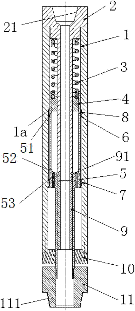
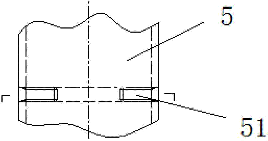
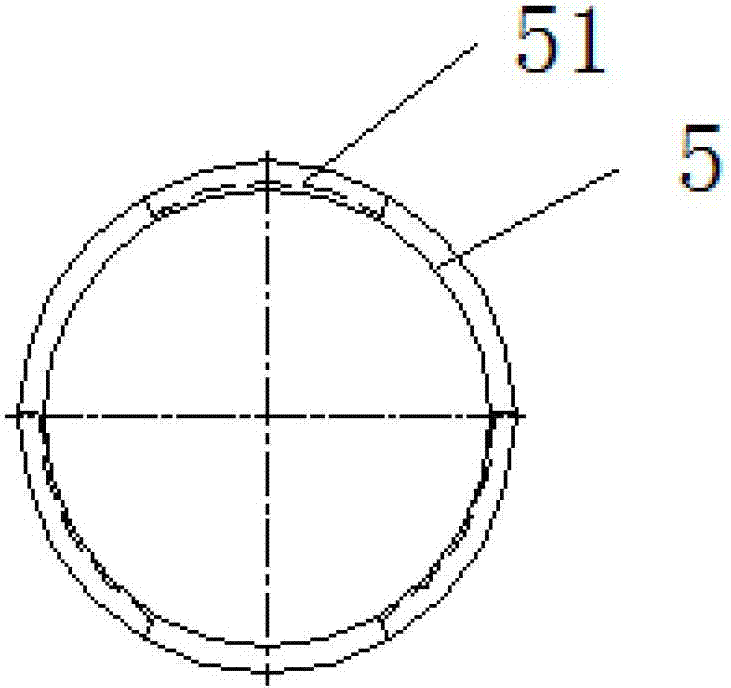
[0022] Such as figure 1 As shown, the device of the present invention includes an outer cylinder 1, and an upper joint 2 with a central hole is inserted in the outer cylinder 1. The central hole at the top of the upper joint 2 is provided with an internal thread 21 connected with the upper drilling tool, and the upper joint 2 passes through the Threaded on the upper mouth of the outer cylinder 1. A spring 3 is sheathed between the middle part of the upper joint 2 and the outer cylinder 1 , the bottom of the spring 3 is connected with an impact hammer 4 , and a sleeve 5 is slidably sandwiched between the impact hammer 4 and the outer cylinder 1 . The middle part of the inner wall of the outer cylinder 1 has a shoulder 1a with an enlarged inner diameter, and a thrust ring 6 is slidably arranged on the inner wall of the outer cylinder 1 below the should...


PUM


Abstract

The invention relates to an underground repetitive shock irritation device and shock irritation method for oil and gas well drilling. The underground repetitive shock irritation device is characterized by comprising an outer cylinder of which the middle part is provided with a shoulder, an upper connector is inserted inside the outer cylinder, and the upper connector is connected with an upper opening of the outer cylinder; a spring which is connected with an impact hammer is sleeved between the middle part of the upper connector and the outer cylinder, and a sleeve is clamped between the impact hammer and the outer cylinder in a sliding way; three structure slots on each of which an arc card is clamped are uniformly distributed on the upper part of the sleeve, and a thrust collar is sleeved at the lower part of each of the structure slots; a stop collar is arranged on the inner wall of the outer cylinder below the thrust collars; a circle of anvil is arranged at the middle part of the inner diameter of the sleeve, a plurality of communicating holes are arranged along the vertical direction of the anvil, an operating sleeve is sleeved on the inner diameter of low-half sleeve in a sliding way, and the operating sleeve is connected at the tail end of the upper connector; a circle of convex plate is arranged at the periphery of the upper opening of the operating sleeve; an external spline which is in sleeve connection with a connector of an internal spline is arranged at the outer diameter of the low-half sleeve, and a lower opening of the outer cylinder is fixedly connected with the connector of the internal spline; and the tail end of the external spline is connected with a lower connector. The repetitive shock irritation device and the shock irritation method disclosed by the invention can be widely used underground repetitive shock irritation in oil and gas well drilling operations in which signals are required.

Description

technical field [0001] The invention relates to a drilling device, in particular to an oil and gas drilling downhole repetitive shock generating device and a shock generating method. Background technique [0002] In oil drilling, in order to identify the formation and the position of the drill bit, etc., it is necessary to use a device that repeats vibrations downhole, so as to identify the downhole state, formation characteristics and drill bit position by collecting the vibration signals generated by the vibration device. etc. purpose. For example, in order to prevent collisions between wellbores during the drilling of cluster wells, this tool is needed to identify the distance between the drill bit and the casing at risk. Because once the wellbores collide, the consequences will be very serious, which will not only cause huge economic losses, but also cause serious environmental pollution. In the past, the main method to solve the anti-collision problem was to adopt tec...

Claims


Application Information

Patent Timeline
Patent Type & Authority Applications(China)
IPC IPC(8): E21B28/00E21B47/095
Inventor 刘刚周建良何保生马加骥王平双董照显武广瑷于长广靳勇曹砚锋文敏
Owner CHINA NAT OFFSHORE OIL CORP
Why Eureka
Try Eureka