Method for improving calibration precision of infrared sensor

An infrared sensor and calibration accuracy technology, which is applied in the infrared field to achieve the effects of improving calibration accuracy, improving temperature measurement accuracy, and overcoming large calibration errors.

Active Publication Date: 2012-12-12
GAOYUAN HIGHWAY MAINTENANCE TECH HENAN PROV
View PDF6 Cites 18 Cited by
  • Summary
  • Abstract
  • Description
  • Claims
  • Application Information

AI Technical Summary

Problems solved by technology

However, this method does not involve improv...

Method used


Image

  • Method for improving calibration precision of infrared sensor
  • Method for improving calibration precision of infrared sensor
  • Method for improving calibration precision of infrared sensor

Examples


Embodiment 1

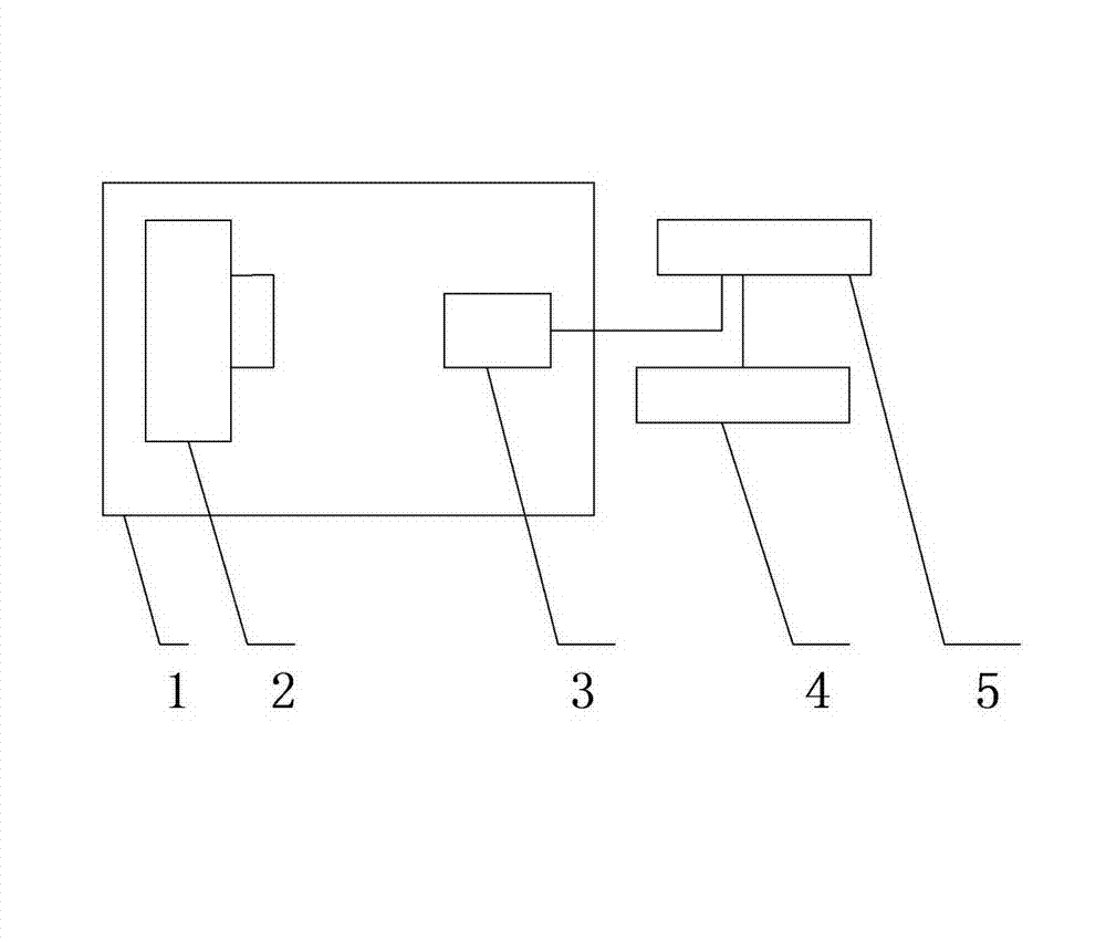
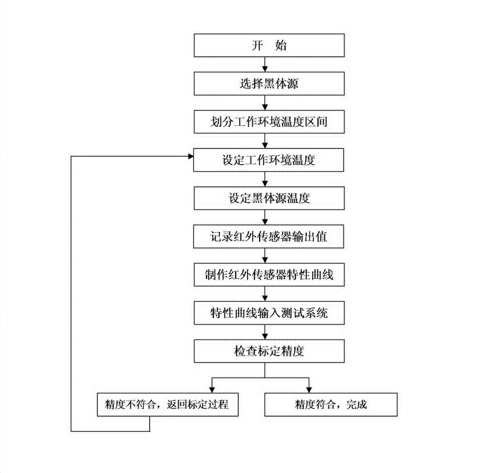
[0030] See attached figure 1 , figure 2 , the implementation of the present invention takes the example of an infrared sensor with an output of -2000 to 2000mv on a cement concrete pavement with a temperature measurement range of -20 to 60°C and an ambient temperature of -20 to 50°C. Including the following steps:

[0031] Step 1: Through the query data, the cement concrete emissivity coefficient is 0.95, select the HFY-302C low-temperature type with emissivity coefficient of 0.95, accuracy ±0.15% (full scale), temperature resolution: 0.01°C, and temperature range: -20~70°C blackbody source.

[0032] Step 2: According to the ambient temperature range of -20-50°C used for infrared sensor temperature measurement, divide 7 ambient temperature intervals at intervals of 10°C (see Table 1), select the bit value of each interval as a representative, and select the appropriate The ambient temperature test chamber sets the working environment temperature respectively.

[0033] Ta...


PUM


Abstract

The invention relates to a method for improving the calibration precision of an infrared sensor. When the infrared sensor is calibrated, firstly, a blackbody origin with the same or similar emission coefficient with/to that of an object to be tested is selected, then, environment temperature intervals at several levels are divided according to the environment temperature range when the infrared sensor works, the work environment temperature of the infrared sensor is set through an environment temperature box or an air conditioner system, the infrared sensor is calibrated under the set environment temperature condition, the on-line test system or an instrument is adopted for recording the voltage or the current value output by the infrared sensor, a data sheet of the current or the voltage output by the infrared sensor corresponding to the standard blackbody temperature at the environment temperature at each level is obtained, the data is subjected to regression analysis, the output characteristic regression equation and curve of the infrared sensor are manufactured, the output characteristic is substituted into a test system, the calibration error is checked in the calibration state, and when the error exceeds the precision requirement, the calibration is carried out again. The method has the advantages that the error can be reduced, the calibration precision is improved, and the influence of the work environment temperature is avoided.

Description

technical field [0001] The invention relates to the field of infrared technology, in particular to a method for improving the calibration accuracy of an infrared sensor. Background technique [0002] In an infrared temperature measuring instrument or system, the signal flow is generally: infrared radiation of the measured object → infrared sensor (probe) → signal circuit → analog-to-digital conversion → data → program calculation according to the output characteristic curve of the infrared sensor (probe) → display output , the corresponding relationship curve between the output of the infrared sensor (probe) and the temperature of the measured object is the output characteristic curve of the infrared sensor (probe). It can be seen that the calibration accuracy of the infrared sensor (probe) and the output characteristic curve of the infrared sensor (probe) are the key factors affecting the accuracy of temperature measurement. Especially during the long-term use of infrared ...

Claims


Application Information

Patent Timeline
IPC IPC(8): G01J5/00
Inventor 刘廷国侯曙光岳学军李忠玉史纪村王军革
Owner GAOYUAN HIGHWAY MAINTENANCE TECH HENAN PROV
Why Eureka
Try Eureka