Semiconductor device and manufacturing method thereof

A manufacturing method and semiconductor technology, applied in semiconductor/solid-state device manufacturing, semiconductor devices, semiconductor/solid-state device components, etc., can solve the problem of large heat transfer loss and achieve the effect of less heat transfer loss

Inactive Publication Date: 2012-12-12
SANKEN ELECTRIC CO LTD
View PDF4 Cites 5 Cited by
  • Summary
  • Abstract
  • Description
  • Claims
  • Application Information

AI Technical Summary

Problems solved by technology

[0006] However, when a chip is flip-chip mounted on a printed circuit board via bumps, an adhesive interface (contact resistance) is generated between the bonding material and the pad, resulting in a large heat transfer loss.

Method used


Image

  • Semiconductor device and manufacturing method thereof
  • Semiconductor device and manufacturing method thereof
  • Semiconductor device and manufacturing method thereof

Examples


Embodiment Construction

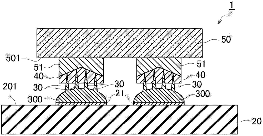
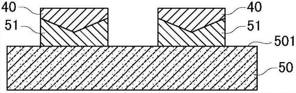
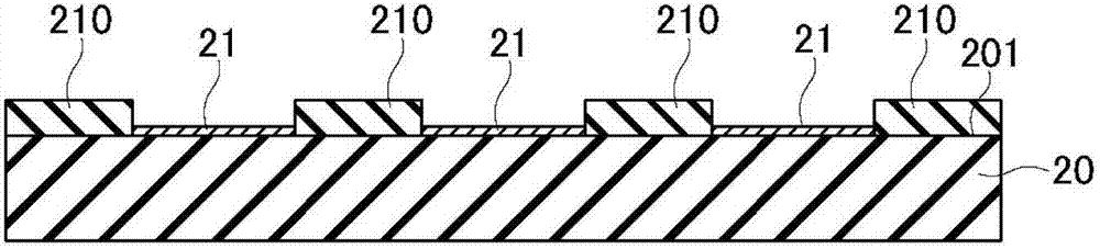
[0037] Next, embodiments of the present invention will be described with reference to the drawings. In the following description of the drawings, the same or similar symbols are attached to the same or similar parts. However, the drawings are schematic diagrams, and it should be noted that the ratio of the thickness of each part and the like are different from actual ones. Therefore, specific thicknesses and dimensions should be judged in consideration of the following descriptions. In addition, it is needless to say that between the drawings, parts where the relationship or ratio of dimensions are different from each other are included.

[0038] In addition, the embodiments shown below are examples of devices and methods for embodying the technical idea of ​​the present invention. In the embodiments of the present invention, the materials, shapes, structures, arrangements, etc. of the constituent parts are not limited to the following . Various modifications can be made to...


PUM


Abstract

The present invention provides a semiconductor device and a manufacturing method thereof. The semiconductor device can be installed with a flip-chip with a little heat loss between a chip and a printing substrate. The semiconductor device comprises: a printing substrate and a chip. The main surface of the printing substrate is configured with a substrate electrode pad with a plurality of spikes composed of graphite on the surface. The main surface of the chip opposite to the substrate electrode pad is provided with a chip electrode pad with conductive resin film contacted with the front ends of the spikes.

Description

technical field [0001] The present invention relates to a semiconductor device having a chip flip-chip mounted on a printed board and a method of manufacturing the same. Background technique [0002] As one method of mounting a chip on which a semiconductor element is formed on a printed board, flip chip mounting is used. For example, by flip-chip mounting a light emitting diode (LED), the number of electrodes arranged on the light emitting surface of the LED can be reduced. Therefore, the luminous efficiency of LED improves. [0003] In order to perform flip-chip mounting of LEDs, a method of forming bumps on electrodes arranged on LEDs, etc. have been studied (for example, refer to Patent Document 1). The LED and the printed board are electrically connected by electrically connecting bumps formed on the LED to pads arranged on the printed board. [0004] As for the bump forming method, there are ball bonding method, printing method, and the like. For example, solder pa...

Claims


Application Information

Patent Timeline
Patent Type & Authority Applications(China)
IPC IPC(8): H01L23/12H01L21/48
CPCH01L24/81H01L24/16H01L2224/16H01L2924/12041H01L2924/00H01L2924/00012
Inventor 杉原一男山本均
Owner SANKEN ELECTRIC CO LTD
Why Eureka
Try Eureka