
Novel special air conditioning system for data center computer room

A technology for air conditioning systems and data centers, applied in cooling/ventilation/heating renovation, electrical components, electrical equipment structural parts, etc. Operational safety hazards, additional cooling capacity in local IT cabinets, etc., achieve the effect of obvious energy saving, cooling capacity saving, and improved distribution.

Inactive Publication Date: 2019-04-19
GUANGZHOU UNIVERSITY
View PDF10 Cites 3 Cited by
  • Summary
  • Abstract
  • Description
  • Claims
  • Application Information

AI Technical Summary

Problems solved by technology

[0005] 2. Due to the low air supply temperature of the air conditioner (about 15-17°C), the overhead floor is used as a floor air supply static plenum box, the temperature inside the box is quite different from the ambient temperature, the heat transfer temperature difference is large, and the cooling capacity loss is relatively large. Large, resulting in a large waste of energy
[0006] 3. If the cable routing space is used under the floor at the same time, it will also lead to poor air supply under the floor and unreasonable distribution of air supply air flow, which will lead to increased energy consumption of the air conditioner
This airflow organization method will cause the air supply and return air volume and temperature of the cooling equipment of the IT cabinet to be uneven. It often occurs that some IT cabinets need to increase the cooling capacity, which cannot ensure that the IT cabinet equipment in the data center computer room is in the best and balanced state. The cooling operation state of the IT cabinet may even cause local overheating of the IT cabinet, which will bring safety hazards to the operation of the equipment in the data center computer room.

Method used


Image

  • Novel special air conditioning system for data center computer room
  • Novel special air conditioning system for data center computer room
  • Novel special air conditioning system for data center computer room

Examples


Embodiment

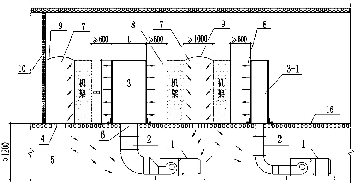
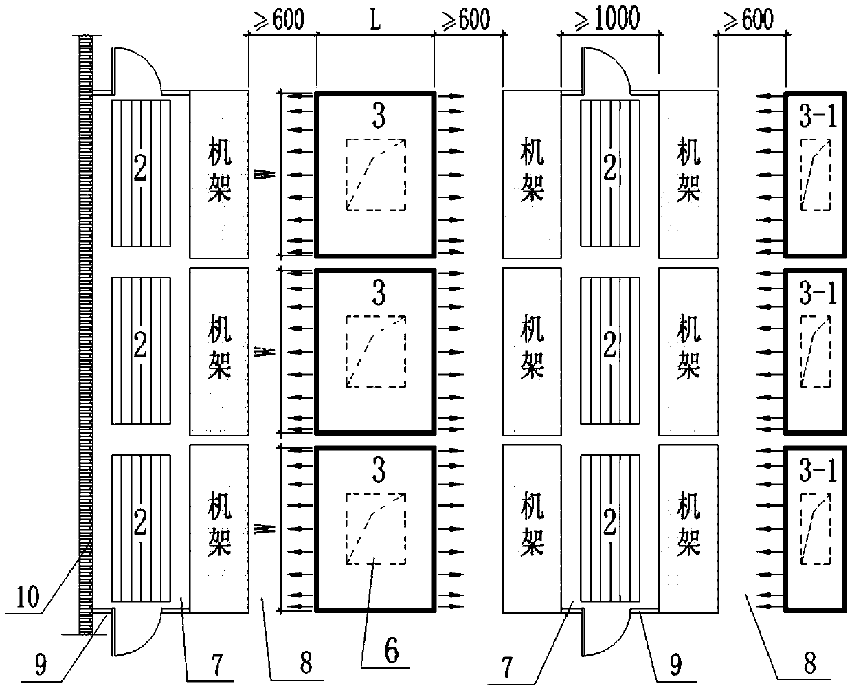
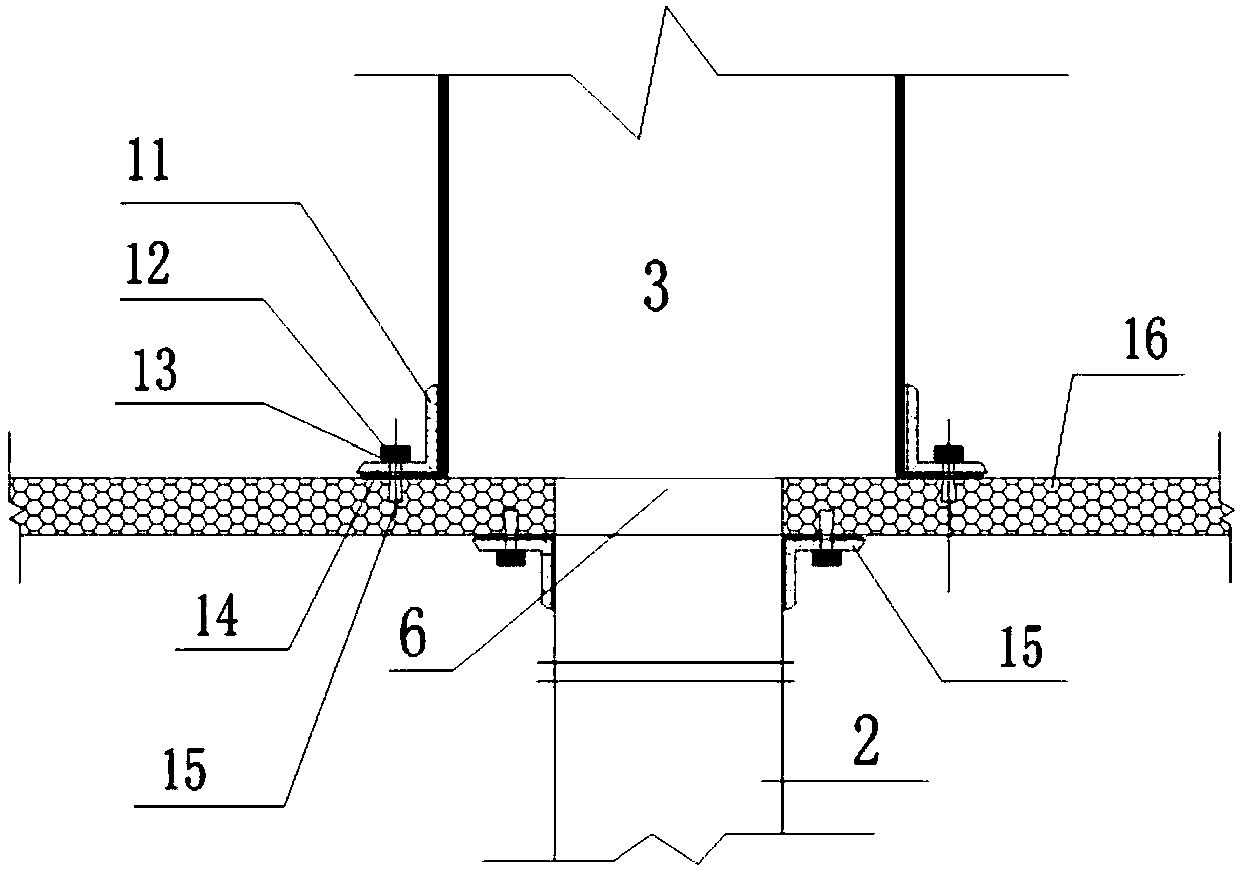
[0024] Such as figure 1 , 2 As shown, the data center computer room air conditioning system of the present invention includes an air processing device 1, an air supply duct 2, an orifice static pressure air supply cabinet 3, a floor return air outlet 4, a floor return air static pressure box 5, and the like. According to the air supply needs, the orifice static pressure air supply cabinet can be set to supply air on one side or two sides, and the air supply on one side is 3-1. The floor of the machine room is elevated, and the overhead floor is used as the floor return air plenum 5 of the air-conditioning system, and the floor return air plenum has the functions of noise reduction and static pressure. The air handling device 1 is arranged in the raised floor or in the air-conditioning machine room close to the data machine room. The orifice static pressure air supply cabinet 3 is arranged in the cold passage 8 of the machine room. The orifice plate static pressure air supply...


PUM


Abstract

The invention relates to a novel special air conditioning system for a data center computer room. The novel special air conditioning system comprises an air treatment device, an air supply duct, a pore plate static-pressure air supply cabinet, a floor air return outlet and a floor air return static-pressure box. The floor air return static-pressure box is a computer room floor overhead layer. Theair treatment device is disposed in the computer room floor overhead layer or in an air conditioner room near the data center computer room. The pore plate static-pressure air supply cabinet is disposed in a cold passage. The floor air return outlet is disposed on the floor of a hot passage. The air is treated by the air treatment device and then is converted into cold air. The cold air passes through the air supply duct, enters the pore plate static-pressure air supply cabinet through an air supply hole at the bottom of the pore plate static-pressure air supply cabinet, and then enters an equipment cabinet for hot and cold exchange. The return air enters the floor air return static-pressure box from the air return outlet and is mixed with the outdoor fresh air in the air treatment device.The lower space of the overhead floor of the computer room is used as the air return static-pressure box to reduce a heat transfer loss. The pore plate static-pressure air supply cabinet and an IT cabinet achieve face-to-face air supply, so as to improve the distribution of the air supply airflow, and ensure the safe and stable operation of the computer room equipment.

Description

technical field [0001] The invention relates to the technical field of air delivery in an air conditioning system, in particular to a new type of special air conditioning system for a data center computer room. Background technique [0002] At present, the main air-conditioning method used in the data center computer room air-conditioning system is the air-conditioning method of supplying air under the floor and returning air from the upper part. The traditional approach is generally: the IT cabinets in the data center computer room are arranged face-to-face and back-to-back, the aisle between the face-to-face of the cabinets is a cold aisle, and the aisle between back-to-back is a hot aisle. The floor of the machine room is elevated, and the overhead floor is used as an air-conditioning air supply plenum, with air supply outlets on the floor of the cold aisle, and return air outlets and return air ducts above the hot aisle. The cold air processed by the air handling device...

Claims


Application Information

Patent Timeline
Patent Type & Authority Applications(China)
IPC IPC(8): H05K7/20
CPCH05K7/20745
Inventor 赵矿美林昌元林琳张沛然
Owner GUANGZHOU UNIVERSITY
Learn More