Air treatment equipment

An air treatment and equipment technology, applied in the field of air treatment equipment, can solve the problems of low energy efficiency and complex system structure in the air treatment process

Pending Publication Date: 2018-07-27
TSINGHUA UNIV
View PDF0 Cites 3 Cited by
  • Summary
  • Abstract
  • Description
  • Claims
  • Application Information

AI Technical Summary

Problems solved by technology

[0003] Therefore, the technical problem to be solved by the present invention is to overcome the defects of low energy efficiency and complex system structure in the existing air treatment process, so as to provide an air treatment equipment with high efficiency, energy saving and simple structure

Method used


Image

  • Air treatment equipment
  • Air treatment equipment
  • Air treatment equipment

Examples


Embodiment 1

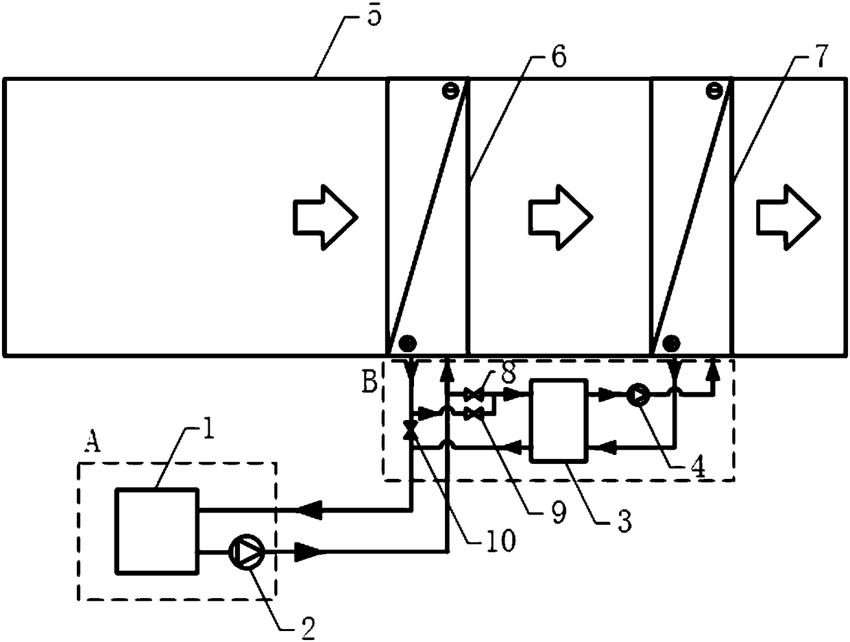
[0041] Such as figure 1 Shown is a specific implementation of an air treatment device, including an air conditioning box 5; two sets of heat exchangers that are sequentially arranged in the air conditioning box 5 as heat exchange devices, and the air passes through the air conditioning box 5 in the air conditioning box 5. The above-mentioned heat exchange device exchanges heat step by step, and the two sets of heat exchangers are respectively the first heat exchanger 6 and the second heat exchanger 7 according to the order in which the air passes through; the cold / heat source unit A outputs cold water or hot water to the outside Water-water heat pump machine 3, the first pipeline that connects the outflow port of the cold / heat source unit A with the inflow port of the first heat exchanger 6, connects the outflow port of the first heat exchanger 6 The second pipeline communicating with the inlet of the cold / heat source unit A, the third pipeline connecting the inlet of the firs...

Embodiment 2

[0051] Such as Figure 4 As shown, the difference between this embodiment and the above embodiment is that it also includes a third regulating valve 19 arranged between the outlet of the circulating water pump 4 on the sixth pipeline and the inlet of the second heat exchanger 7, and the The sixth pipeline, the eighth pipeline located in the downstream part of the third regulating valve 19 communicated with the first pipeline, the fourth regulating valve 20 located in the eighth pipeline, and the seventh The pipeline communicates with the ninth pipeline located downstream of the fifth regulating valve 10 in the second pipeline. When the water-water heat pump 3 is selected to run, the third regulating valve 19 is opened and the fourth regulating valve is closed. Valve 20; when choosing to stop running the water-water heat pump machine 3, close the first regulating valve 8, close the second regulating valve 9, close the third regulating valve 19, open the fourth regulating valve ...


PUM


Abstract

The invention provides air treatment equipment. The air treatment equipment comprises an air conditioning box, a heat exchange device, a cold/heat source unit, a water-water heat pump unit and a controller, wherein the heat exchange device comprises at least two groups of heat exchangers which are sequentially arranged in the air conditioning box, and when air flows in the air conditioning box, the air is subjected to heat exchange with the heat exchange device in a step-by-step mode; the cold/heat source unit is used for outputting cold/hot water outside; and the water-water heat pump unit comprises a water-water heat pump machine, a first pipeline assembly and a second pipeline assembly, wherein the first pipeline assembly communicates with the first end of the water heat pump machine and is connected with the water-water heat pump machine, the second end of the water heat pump machine communicates with the second pipeline assembly, and any two sets of heat exchangers in the heat exchange device communicate with water-water heat pump unit. According to the air treatment equipment the cold water temperature is greatly improved, the heat supply hot water temperature is reduced, and therefore the energy efficiency of the heat source unit is improved; a cold source or a heat source with a single temperature is adopted, so that the complexity degree of the cold source and the heat source and a pipe network is greatly reduced, and engineering implementation and operation control are facilitated; and the air is subjected to step-by-step heat exchange in the heat exchange device, so that the temperature change of the air is matched with the temperature change of cold water and hot water, and the heat transfer loss is reduced.

Description

technical field [0001] The invention relates to the technical field of air conditioning, in particular to an air treatment device. Background technique [0002] Conventional air treatment uses a single temperature cold source or heat source for air treatment, such as using low-temperature cold water (such as 7°C) to achieve the effect of cooling and dehumidification, or using high-temperature hot water (such as 50°C) to achieve the purpose of heating air, resulting in cold source Or the pressure ratio of the heat source is large and the efficiency is low. However, during the air treatment process, the temperature rise or drop of the air is large, and it is possible to use different grades of cold and heat sources for air segmental treatment, thereby reducing the pressure ratio of the cold and heat sources and improving efficiency. Using dual / multiple cold and heat sources can realize the above-mentioned segmented air treatment process, but this leads to complex cold and hea...

Claims


Application Information

Patent Timeline
Patent Type & Authority Applications(China)
IPC IPC(8): F24F5/00F24F3/153F24F13/30F24F11/84F24F11/65
CPCF24F5/00F24F3/153F24F13/30
Inventor 王宝龙崔梦迪石文星李先庭程作
Owner TSINGHUA UNIV
Why Eureka
Try Eureka