Multistage gas liquefaction plant driven by loop multistage thermoacoustic engine

A thermoacoustic engine and liquefaction device technology, applied in the directions of liquefaction, refrigeration and liquefaction, gas cycle refrigerators, etc., can solve the problems of large heat transfer loss, low efficiency, inability to achieve gas cascade cooling, etc., and achieve large cooling capacity, energy The effect of high density and good application prospects

Active Publication Date: 2016-02-17
TECHNICAL INST OF PHYSICS & CHEMISTRY - CHINESE ACAD OF SCI
View PDF7 Cites 3 Cited by
  • Summary
  • Abstract
  • Description
  • Claims
  • Application Information

AI Technical Summary

Problems solved by technology

However, if this system is used to complete the overall liquefaction process of liquefying normal-temperature gas to low-temperature liquid, it will cause a large heat transfer loss due to the inability to realize gas cascade cooling, and the efficiency is very low

Method used


Image

  • Multistage gas liquefaction plant driven by loop multistage thermoacoustic engine
  • Multistage gas liquefaction plant driven by loop multistage thermoacoustic engine
  • Multistage gas liquefaction plant driven by loop multistage thermoacoustic engine

Examples


Embodiment 1

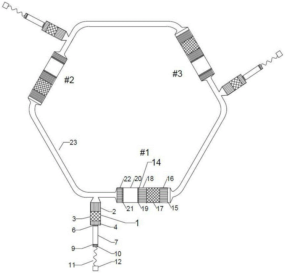
[0028] image 3 It is a structural schematic diagram of a loop multi-stage thermoacoustic engine-driven gas multi-stage (four-stage) liquefaction device (embodiment 1) of the present invention. It consists of 3 thermoacoustic engine units (1#, 2#, 3#) connected end-to-end through a resonance tube 23 to form a loop structure and 3 pulse tube refrigerator units 1; each thermoacoustic engine unit 14 is composed of DC Suppressor 15, engine main cooler 16, engine regenerator 17, heater 18, high temperature end laminar fluidization element 19, heat buffer pipe 20, engine room temperature end laminar fluidization element 21 and engine secondary cooler 22; A pulse tube refrigerator unit 1 is bypassed at the outlet of the engine subcooler 22 of a thermoacoustic engine unit 14;

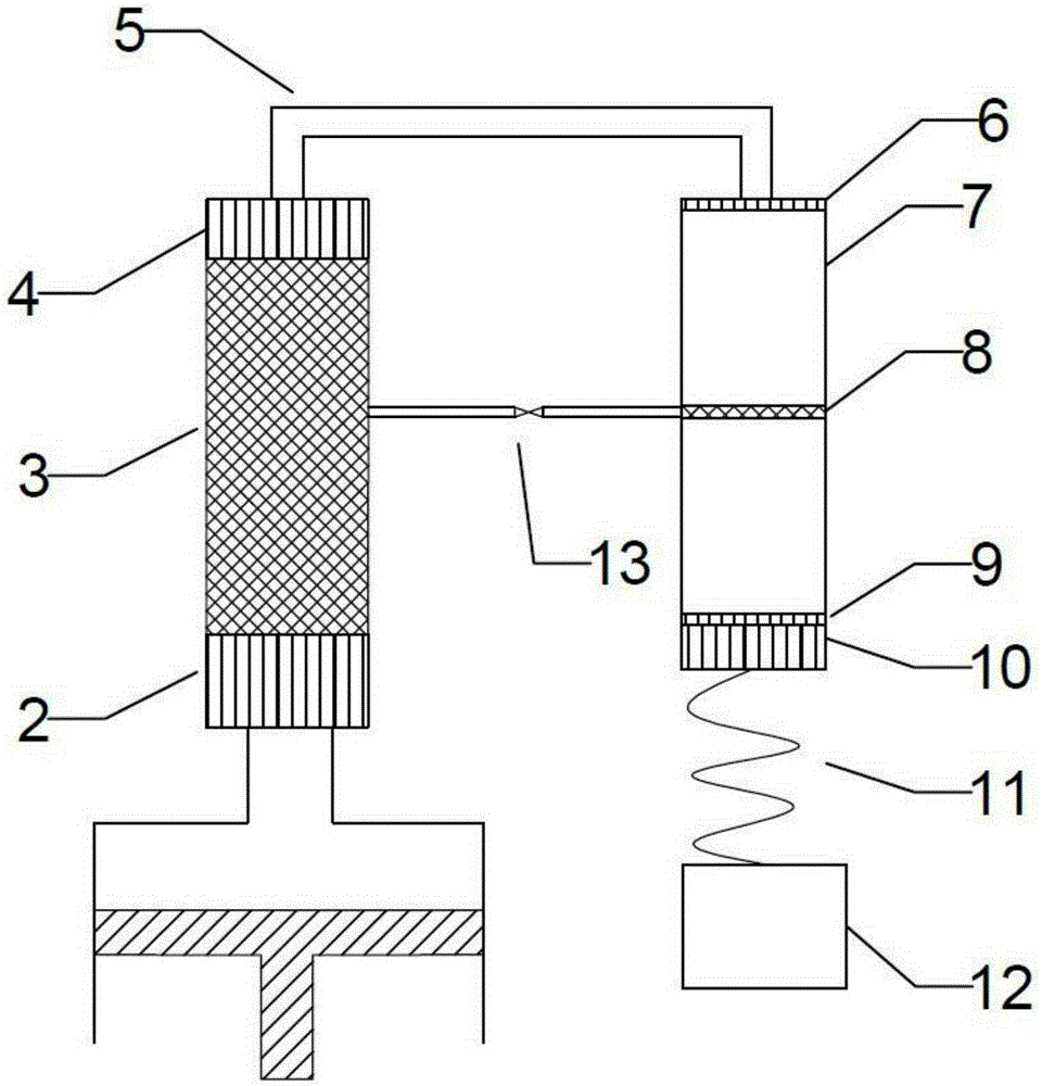
[0029] In this embodiment, each pulse tube refrigerator unit 1 is composed of the main water cooler 2 of the refrigerator, the 4-stage refrigeration unit connected in series, the connecting pipe 5, the pulse t...

Embodiment 2

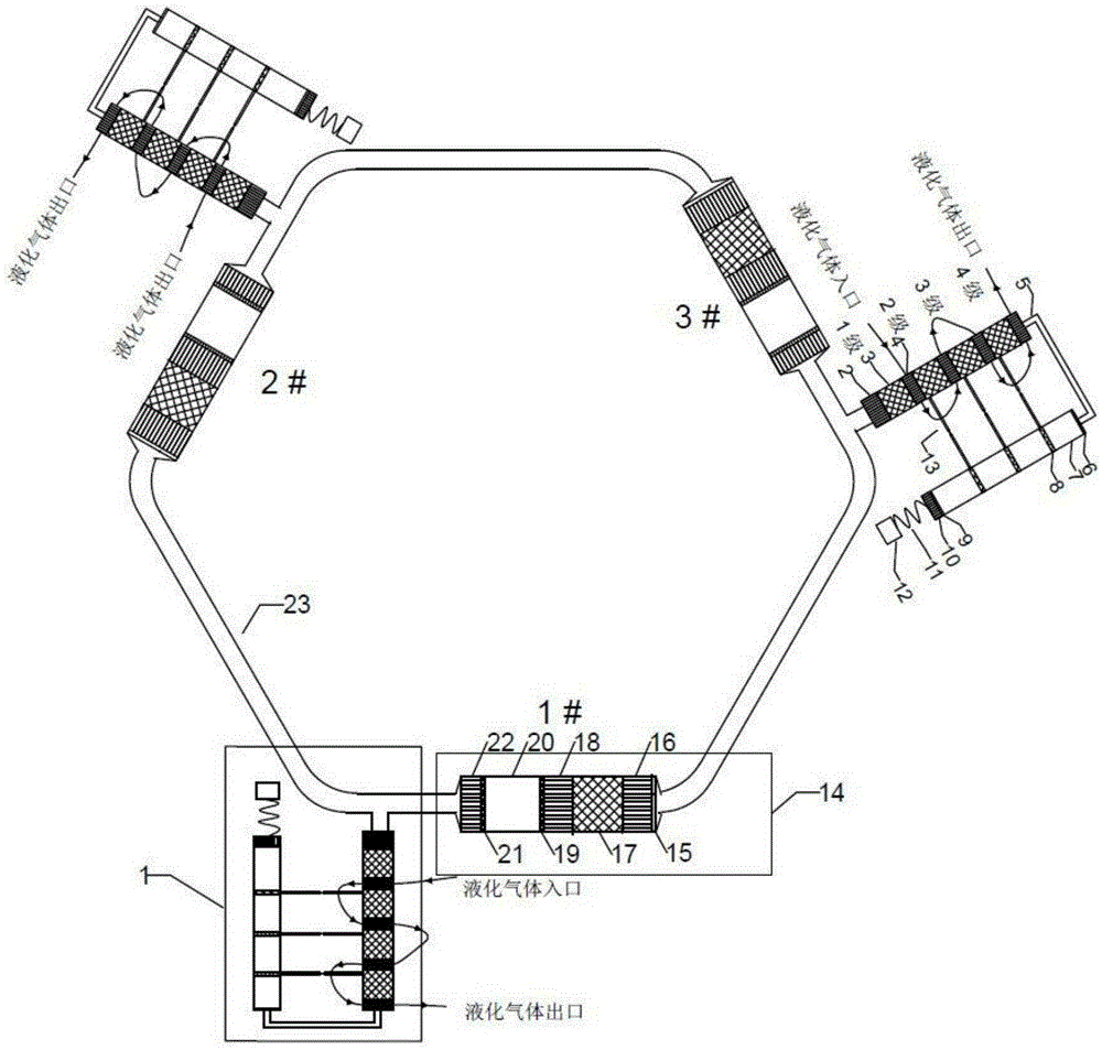
[0032] Figure 4 It is a schematic structural diagram of a gas multistage (4 stage) liquefaction device (embodiment 2) driven by a loop multistage thermoacoustic engine of the present invention; the device is passed by 3 thermoacoustic engine units (1#, 2#, 3#) The resonant tube 23 is connected end to end to form a loop structure and three pulse tube refrigerator units 1; each thermoacoustic engine unit 14 is composed of a DC suppressor 15, an engine main cooler 16, an engine regenerator 17, a heater 18, High-temperature end laminar fluidization element 19, heat buffer pipe 20, engine room temperature end laminar fluidization element 21 and engine sub-cooler 22; the exit of engine sub-cooler 22 of each thermoacoustic engine unit 14 is bypassed by a pulse tube refrigeration machine unit 1;

[0033] In each pulse tube refrigerator unit 1, a refrigerator regenerator 3 and a low-temperature end heat exchanger 4 connected in series form a first-stage refrigeration unit, and this e...


PUM


Abstract

The invention discloses a multistage gas liquefaction plant driven by a loop multistage thermoacoustic engine. The multistage gas liquefaction plant comprises M thermoacoustic engine units and pulse tube refrigerating machine units, wherein the pulse tube refrigerating machine units are connected with the outlets of the thermoacoustic engine units in a by-pass manner; M is a positive integer ranging from 3 to 6; a refrigerating unit comprises a refrigerating machine regenerator and a low-temperature end heat exchanger; each pulse tube refrigerating machine unit comprises two or more refrigerating units; multiple by-pass pipelines are arranged between each refrigerating machine regenerator and a corresponding pulse tube, so that the refrigerating machine regenerator and the corresponding pulse tube are connected to form at least one by-pass airflow passage; acoustic power generated through self-excitation of the thermoacoustic engine has thermoacoustic conversion in the refrigerating machine regenerators; the multiple low-temperature end heat exchangers are maintained under different refrigerating temperatures; and the to-be-liquefied gas sequentially passes through all low-temperature end heat exchangers to be liquefied in a temperature stepped decrease manner. The multistage gas liquefaction plant has no moving part, and is compact in structure and high in power density; the loop structure enables the engine units to be in the traveling wave phase; the multipath bypass structure realizes gas expansion refrigeration to improve the efficiency of a pulse tube refrigerating machine; and in addition, the multistage refrigerating units reduce the gas temperature in a stepped manner to effectively reduce the irreversible heat transfer loss.

Description

technical field [0001] The invention belongs to a gas liquefaction device in the field of gas liquefaction, in particular to a gas multistage liquefaction device driven by a loop multistage thermoacoustic engine. Background technique [0002] Liquefaction is the process by which a substance changes from a gaseous state to a liquid state. Since the volume of the gas after liquefaction will become one thousandth of its original volume, which is convenient for storage and transportation, some gases are usually liquefied in reality. There are two ways to achieve liquefaction, one is to lower the temperature, and the other is to compress the volume. Any gas can be liquefied when the temperature drops low enough. Therefore, how to manufacture a cryogenic refrigerator with high reliability, long life, high efficiency, and ability to cascade liquefy gas has become a concern. [0003] A thermoacoustic engine is a device that uses pipes and heat exchangers to obtain a suitable soun...

Claims


Application Information

Patent Timeline
Patent Type & Authority Applications(China)
IPC IPC(8): F25J1/02
CPCF25J1/0225F25B9/145F25B2309/1407F25B2309/1425F25B2309/1426F25J1/001F25J1/0015F25J1/0022F25J2270/91F25J1/0209
Inventor 罗二仓徐静远张丽敏陈燕燕戴巍胡剑英吴张华
Owner TECHNICAL INST OF PHYSICS & CHEMISTRY - CHINESE ACAD OF SCI
Why Eureka
Try Eureka