Antenna for receiver and emitter of wireless microphone, and receiver and emitter arranged with antenna

A technology for wireless microphones and transmitters, applied to antenna supports/mounting devices, microphone ports/microphone accessories, etc., which can solve problems such as damage, breakage, and inability to rotate the connection structure

Inactive Publication Date: 2012-12-12
CHANFUL VOICE TECHNIC
View PDF4 Cites 6 Cited by
  • Summary
  • Abstract
  • Description
  • Claims
  • Application Information

AI Technical Summary

Problems solved by technology

[0003] However, the above-mentioned antenna structure can only pivot left and right on one plane, and cannot rotate to swing on different planes, so that the angle and direction where the antenna can send and receive signals are too narrow and limited, and it is impossible for the user to adjust the antenna in a wide range Therefore, the antenna structure provided by Chinese Taiwan Patent Nos. M375995 and 572371 can rotate 360 ​​degrees and can pivot and swing at the same time. It mainly includes a rotating unit and a connecting unit, and the rotating unit and the connecting unit can be connected. Rotationally connected, and the antenna body is pivoted on the rotating unit, and the connecting unit is fixed on the wireless receiver and transmitter. Through this design, the antenna pivoted on the rotating unit can not only swing left and right to adjust the position In addition, the antenna can also rotate 360 ​​degrees relative to the connecting unit, so that the antenna can be rotated to different planes while pivoting left and right, so that the antenna can be adjusted to change directions and angular positions in multiple directions and not limited to a single plane
[0004] However, the rotating unit of the antenna can only rotate on a single axis relative to the connecting unit, but the rotating unit cannot swing relative to the connecting unit to change the angle between the two, so that the adjustable position of the antenna still has a dead

Method used


Image

  • Antenna for receiver and emitter of wireless microphone, and receiver and emitter arranged with antenna
  • Antenna for receiver and emitter of wireless microphone, and receiver and emitter arranged with antenna
  • Antenna for receiver and emitter of wireless microphone, and receiver and emitter arranged with antenna

Examples


Embodiment Construction

[0036] The following examples illustrate possible embodiments of the present invention, but are not intended to limit the protection scope of the present invention.

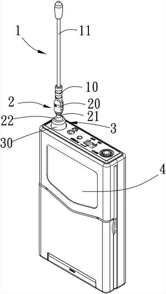
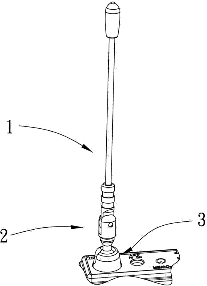
[0037] Please refer to figure 1 and figure 2 , the present invention provides an antenna for a wireless microphone receiver and transmitter, which mainly includes an antenna body 1 , a connecting body 2 and a base 3 .

[0038] The antenna body 1 includes an antenna rod body 11 and a joint seat 10 connected with the antenna rod body, the connecting body 2 includes a pivot portion 20, a neck portion 21 and a ball 22, the neck portion 21 is connected to the pivot joint Between the part 20 and the ball 22, and the pivot part 20 and the joint base 10 are pivotally connected to each other. More specifically, the antenna body 1 mainly includes an antenna rod body 11 and a joint base 10, the antenna rod body 11 is fixed at one end of the joint base 10, and the pivot portion 20 of the connecting body 2 is formed with t...


PUM


Abstract

The present invention provides an antenna for the receiver and emitter of a wireless microphone, including an antenna body which contains an antenna rod body and a connecting seat in connection with the antenna rod body; a connecting body, including a pivot connection portion, a neck portion, and a sphere, wherein the neck is connected between the pivoting portion and the sphere, and the pivot portion and the connecting seat are pivotally connected to each other; a base having an annular retaining wall, the retaining wall encloses an accommodating space having at least one opening, the maximum diameter of the opening is smaller than the maximum diameter of the sphere, and the sphere is located in the accommodating space so that the connecting body is rotatably connected to the base. The antenna body of the present invention, in addition to pivoting movement relative to the connecting body, can be rotated relative to the base, while the connecting body may optionally be swung to rotate on a different axis so that the antenna body can yaw in all directions and adjust in rotation. The antenna can still maintain good as new connecting structure even being repeatedly pulled to adjust.

Description

technical field [0001] The invention relates to an antenna for a receiver and a transmitter of a wireless electronic device, in particular to an antenna for a receiver and a transmitter of a wireless microphone. Background technique [0002] In the prior art, wireless electronic equipment needs to be equipped with an antenna to receive or transmit wireless signals, because the effect of sending and receiving wireless signals often directly affects the performance and performance of these wireless devices, and because the transmission of wireless signals is easy Interference or restriction by external conditions greatly reduces the effect of signal transmission and reception. Therefore, the antennas installed in these wireless devices can be adjusted to change their angle and direction, so that users can adjust the angle of the antenna to achieve the best transmission and reception effect. . In the existing antenna, a base is fixed on the electronic equipment, and the antenn...

Claims


Application Information

Patent Timeline
IPC IPC(8): H01Q1/24H04R1/08
Inventor 刘春隆
Owner CHANFUL VOICE TECHNIC
Why Eureka
Try Eureka