Rotary counter weight mechanism and crane

A crane and counterweight technology, applied in cranes and other directions, can solve problems such as being unsuitable for small and medium-sized tire-mounted cranes, unadjustable center of gravity of fixed counterweights, increasing manufacturing costs, etc., to improve lifting performance and safety performance, and a simple structure. , the effect of low manufacturing cost

Active Publication Date: 2012-12-19
SANY MARINE HEAVY IND +1
View PDF7 Cites 14 Cited by
  • Summary
  • Abstract
  • Description
  • Claims
  • Application Information

AI Technical Summary

Problems solved by technology

If the counterweight unit of the crane is fixed, then the stabilizing moment is a fixed value. When the lifting moment exceeds the stabilizing moment, the outriggers at the rear of the vehicle chassis will tilt up, posing a safety hazard.
On the other hand, the center of gravity of the fixed counterweight cannot be adjusted, and a heavier counterweight is bound to be required to increase the stabilizing moment, which increases the manufacturing cost
[0004] If the counterweight unit of the crane adopts a linear movable structure, the linear movable counterweight needs to be equipped with slide rails, but the original tire-type crane has a compact structure and does not have enough space. Setting the linear movable counterweight will inevitably change the original crane structure, resulting in increased manufacturing costs. High, complex structure, not suitable for small and medium-sized rubber-tyred cranes and some small cranes

Method used


Image

  • Rotary counter weight mechanism and crane
  • Rotary counter weight mechanism and crane

Examples


Embodiment Construction

[0021] The specific implementation manners according to the present invention will be described below in conjunction with the accompanying drawings. It should be noted that, in the case of no conflict, the embodiments of the present application and the features in the embodiments can be combined with each other.

[0022] In the following description, many specific details are set forth in order to fully understand the present invention. However, the present invention can also be implemented in other ways different from those described here. Therefore, the protection scope of the present invention is not limited by the specific implementation disclosed below. Example limitations.

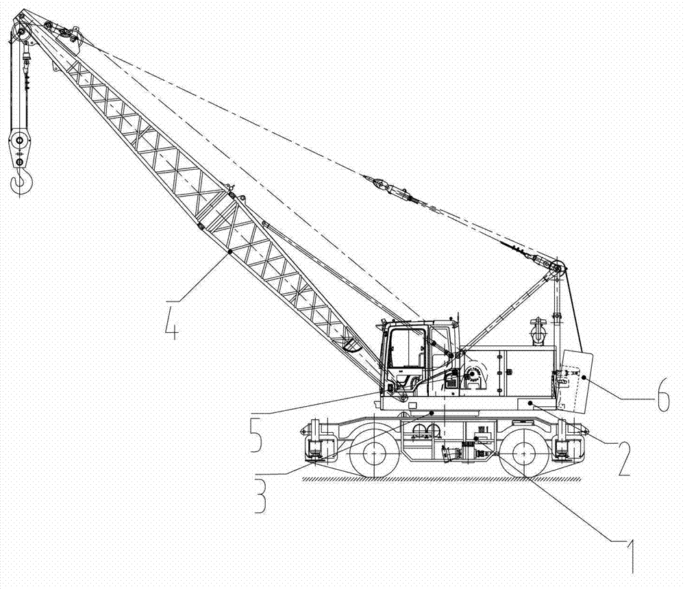
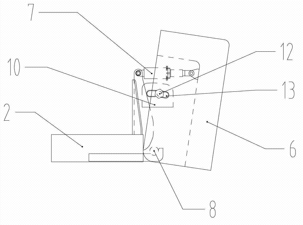
[0023] Such as figure 1 and figure 2 As shown, the crane includes a vehicle chassis 1, a boom 4, a luffing mechanism (not shown in the figure), a slewing support 3, and a lifting mechanism 5. The frame 2 is connected to the vehicle chassis 1 through the slewing support 3, and the slewing support 3...


PUM


Abstract

The invention provides a rotary counter weight mechanism comprising a rack, a counter weight unit and a driving device; the counter weight unit and the rack are hinged by using a pin shaft; and the driving device is used for driving the counter weight unit to swing relative to the rack. Therefore, the lifting property is improved without increasing the weight of the whole crane or changing the contour dimension; and the crane is simple in structure, excellent in safety and low in manufacturing cost.

Description

technical field [0001] The invention relates to the field of engineering machinery, and more specifically relates to a rotatable counterweight mechanism and a crane with the rotatable counterweight. Background technique [0002] The structural parts of the tire crane are designed according to the maximum load when the minimum amplitude is lifted. At this time, the moment of the load on the whole machine is the maximum limit situation, but in the actual work, the medium and long jib is used, and the medium load (generally not exceeding 60% of the rated load), there is a large margin in the strength of structural members. However, due to insufficient stabilizing torque, the lifting performance of the whole machine is insufficient, which reduces the actual lifting capacity of the whole machine, and the lifting performance of the whole machine can be increased by increasing the counterweight. [0003] At present, the prior art crane counterweight unit has a fixed type and a lin...

Claims


Application Information

Patent Timeline
Patent Type & Authority Applications(China)
IPC IPC(8): B66C23/76
Inventor 高王灿董元俊陈玲
Owner SANY MARINE HEAVY IND
Why Eureka
Try Eureka