Well-drilling safety intelligent monitoring method and well-drilling safety monitoring alarming device

An intelligent monitoring and drilling technology, applied in wellbore/well components, earthwork drilling, flushing wellbore, etc., can solve problems affecting accurate measurement, flow meter failure, alarm, etc., to increase safety and stability, increase stability , Guarantee the effect of work

Inactive Publication Date: 2012-12-19
SICHUAN GUANGHAN HENGSHENG PETROLEUM EQUIP
View PDF18 Cites 9 Cited by
  • Summary
  • Abstract
  • Description
  • Claims
  • Application Information

AI Technical Summary

Problems solved by technology

[0003] The problem with the above method is: firstly, this method does not monitor and alarm the mud outlet flow, but only alarms by monitoring the liquid volume in the tank
During the drilling mud circulation process, the blades of the flowmeter and the rotating shaft will sti...

Method used


Image

  • Well-drilling safety intelligent monitoring method and well-drilling safety monitoring alarming device
  • Well-drilling safety intelligent monitoring method and well-drilling safety monitoring alarming device
  • Well-drilling safety intelligent monitoring method and well-drilling safety monitoring alarming device

Examples


Embodiment 1

[0026] A drilling safety intelligent monitoring method mainly consists of the following steps:

[0027] S1: Measurement step: measure the liquid flow velocity and liquid temperature at the outlet of the overflow pipe; measure the liquid volume in the mud tank;

[0028] S2: Early warning step: if the liquid flow velocity variation reaches the first velocity increment warning value, such as 1L / s, a well kick warning is performed; if the fluid flow velocity variation reaches the second velocity increment warning value, For example, 2L / s, a well kick alarm will be issued; if the liquid flow velocity change reaches the third speed increment warning value, such as 3L / s, an emergency well kick alarm will be issued;

[0029] At the same time, if the liquid flow velocity variation reaches the first velocity decrement early warning value, such as -1L / s, a lost circulation warning is performed; if the fluid flow velocity variation reaches the second velocity decrement early warning value...

Embodiment 2

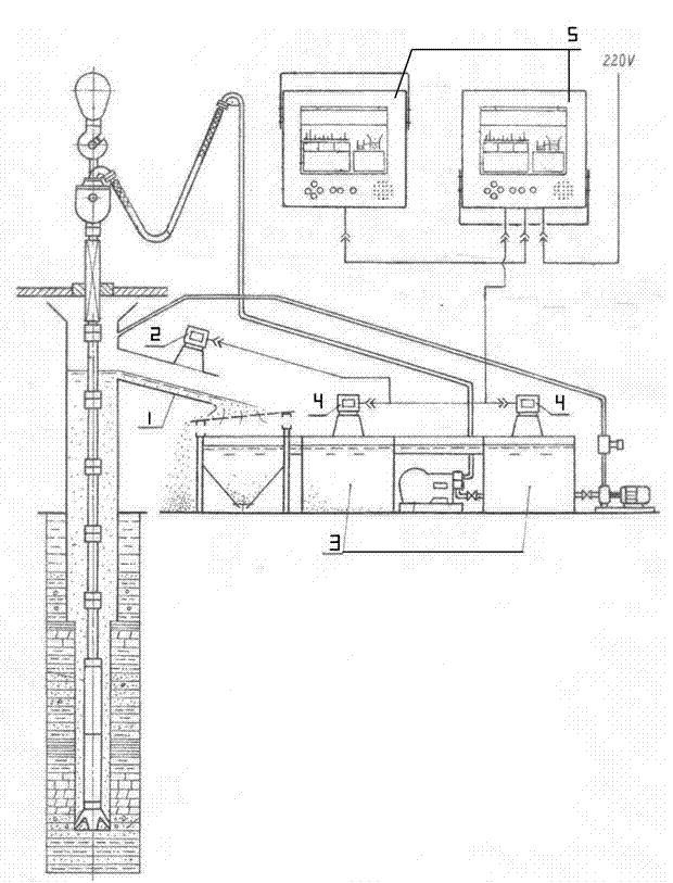
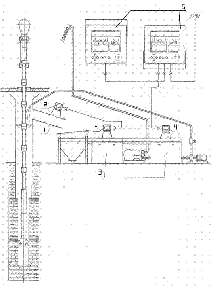
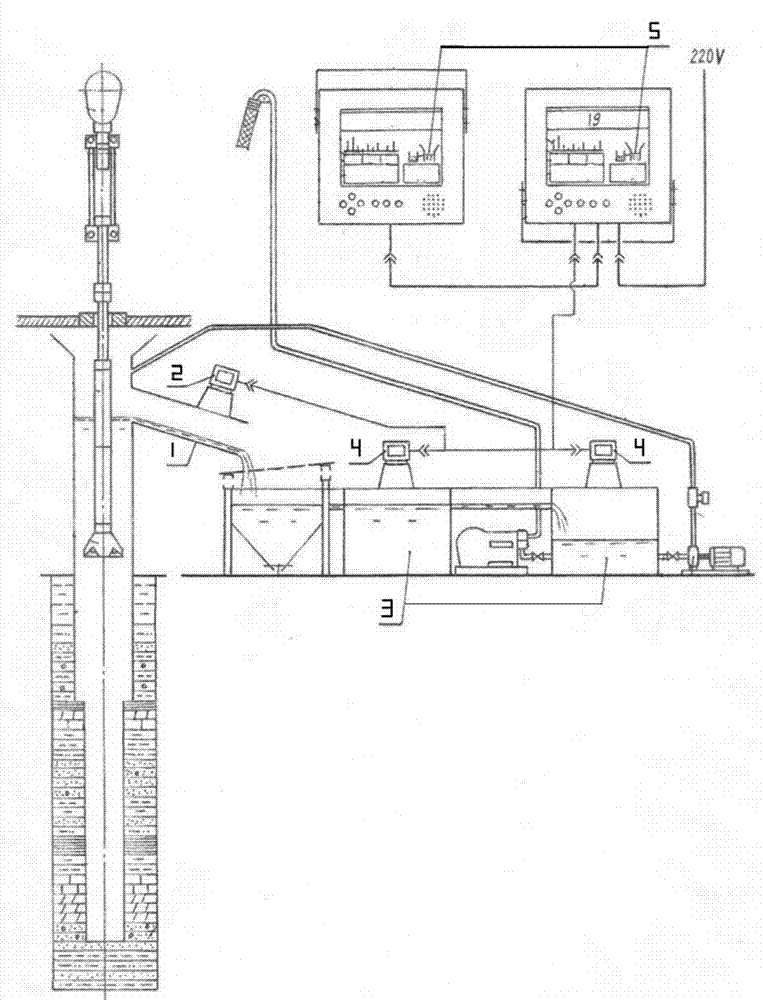
[0036] A drilling safety monitoring and alarming device is composed of an outlet flowmeter, a liquid level transmitter, a sound alarm and at least two monitoring terminals.

[0037] The outlet flowmeter includes a flowmeter bracket, a flowmeter casing, a flowmeter sonar sensor, a flowmeter main control board, a flowmeter digital tube and a flowmeter temperature sensor; the flowmeter casing is a cubic steel with a transparent tempered glass window. Shell; the flowmeter bracket bolts are connected to the lower part of the flowmeter casing in the direction of gravity; the flowmeter sonar sensor is installed on the side of the flowmeter casing connected to the flowmeter bracket, and is connected to the flowmeter main control board through wires; the flowmeter main control board The board is installed inside the flowmeter housing and connected to the digital tube of the flowmeter through wires; the digital tube of the flowmeter is installed on the side of the flowmeter housing with ...


PUM


Abstract

The invention discloses a well-drilling safety intelligent monitoring method for monitoring liquid flow speed at an outlet of an overflow pipe and alarming while achieving an alarming condition. According to the well-drilling safety intelligent monitoring method, the well kick or well leakage dangerous case can be timely detected in the early days. The monitoring on the liquid flow speed is in real time, so that the misinformation situation as a mud tank is avoided and the safety stability is increased. The invention also discloses a well-drilling safety monitoring alarming device which comprises an outlet flow meter utilizing a sonar sensor to monitor the liquid flow speed at the outlet. Due to the non-contact property of the sonar sensor, the stability of the work of the outlet flow meter is ensured, the conditions, such as fault operation, caused by the blocking of the mud slurry are avoided, and the stability of the well-drilling safety monitoring alarming device is increased.

Description

technical field [0001] The invention belongs to the field of petroleum and natural gas exploration and production, and in particular relates to a method for intelligently monitoring the safety of drilling mud by using a sensor and a device for monitoring and alarming drilling safety. Background technique [0002] Existing drilling mud liquid level monitoring methods, such as the disclosed "method and system for tripping and tripping mud automatic injection" disclosed by the Chinese Patent Office Publication No. Method", one is to automatically monitor the fluid volume and total fluid volume of the mud tank in the drilling cycle, and when the fluid volume increases and decreases continuously exceeds the set value by 2m 3 The second is to monitor whether there is mud at the outlet of the overflow pipe of the drilling cycle, and to perform early warning of well leakage when the drilling circulation mud has no liquid flow, and to perform an early warning of well leakage at t...

Claims


Application Information

Patent Timeline
IPC IPC(8): E21B21/08
Inventor 邓福泉曾鸣易荣孙先国
Owner SICHUAN GUANGHAN HENGSHENG PETROLEUM EQUIP
Why Eureka
Try Eureka