

Hydraulic damping device
A technology of hydraulic damping and damping device, which is applied in the direction of fluid pressure actuating device, servo motor assembly, mechanical equipment, etc., can solve the problems of noise, host vibration, and inability to meet the requirements of separate control and adjustment.
Inactive Publication Date: 2012-12-19
LANZHOU UNIVERSITY OF TECHNOLOGY
View PDF4 Cites 5 Cited by
- Summary
- Abstract
- Description
- Claims
- Application Information
AI Technical Summary
Problems solved by technology
Generally, the reversing movement of the spool of the hydraulic control spool valve is driven by hydraulic pressure, and the reset movement is driven by spring force. The movement has asymmetrical characteristics, and most of them are low-damping systems. Especially for large-flow hydraulic systems, the mass of the spool is large. , the inertia of the reversing movement is large. In order to make the spool reversing movement smooth and fast, at present, in engineering practice, the form of setting an oil return damping hole in the spool reversing oil circuit is often used to adjust the motion damping of the spool. The damping device has the advantages of simple structure and good craftsmanship, but it cannot satisfy the separate control and adjustment of the damping process of the positive and negative reversing movement of the slide valve hydraulic control valve core, which cannot fully match the asymmetry of the two-way movement of the valve core. The stability and rapidity of the spool changeover of the spool valve will deteriorate, which will easily cause overshoot fluctuations in the flow or pressure of the system, and cause problems such as vibration and noise of the main engine.
Method used
View moreImage
Smart ImageViewing Examples

Examples
Embodiment Construction
Login to View More PUM
 Abstract
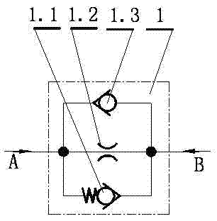
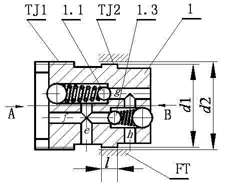
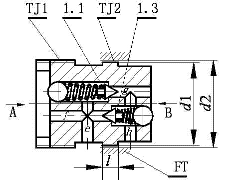
The invention relates to a hydraulic damping device for controlling and adjusting a dynamic process of a reversing motion of a valve core of a hydraulic controlled slide valve type hydraulic control valve. The device is of an integrated structure, and consists of a first one-way valve, a damping hole and a second one-way valve. An external screw thread is processed at the outer end of the device and the external screw thread can be inserted, screwed and installed in the hydraulic control valve. The first one-way valve, the damping hole and the second one-way valve are connected in parallel, and the first and second one-way valves are arranged opposite to each other. The hydraulic damping device is compact in structure and convenient to arrange, and the damping effects in positive and reverse motions of the valve core of the hydraulic controlled slide valve type hydraulic control valve can be respectively controlled and adjusted, and the valve core of the slide valve reveres stably and quickly.
Description
technical field [0001] The invention relates to a hydraulic damping device used for the control and adjustment of the dynamic process of the spool reversing movement of a hydraulic control slide valve type hydraulic control valve. Background technique Hydraulic control spool type hydraulic control valves are widely used in valve-controlled hydraulic systems. The dynamic process of the spool movement is related to the dynamic process of the main engine movement. Comfort plays a big role. Generally, the reversing movement of the spool of the hydraulic control spool valve is driven by hydraulic pressure, and the reset movement is driven by spring force. The movement has asymmetrical characteristics, and most of them are low-damping systems. Especially for large-flow hydraulic systems, the mass of the spool is large. , the inertia of the reversing movement is large. In order to make the spool reversing movement smooth and fast, at present, in engineering practice, the form of...
Claims
Login to View More Application Information
Patent Timeline
 IPC IPC(8): F15B13/02
Inventor李桂花王建森冀宏魏列江
OwnerLANZHOU UNIVERSITY OF TECHNOLOGY