Grinding device of licker-in grinding and covering machine

A technology for grinding licker-in rollers and grinding, which is applied in the directions of grinding drive devices, grinding machine parts, grinding/polishing equipment, etc. Fixing and moving are prone to problems such as crawling and jittering, so as to achieve the effect of reducing grinding wheel correction devices, high lateral reciprocating motion accuracy, and smooth commutation.

Active Publication Date: 2013-08-28
无锡立达纺织机械器材有限公司
View PDF6 Cites 4 Cited by
  • Summary
  • Abstract
  • Description
  • Claims
  • Application Information

AI Technical Summary

Problems solved by technology

[0006] First, the existing grinding method of the licker-in machine adopts a single-roller cylindrical guide rail, a built-in reciprocating screw rod, and a nut-opening structure. Due to the influence of machining accuracy and assembly accuracy, the grinding head rotation accuracy and The movement accuracy is not high, and the grinding head is not smooth when changing directions, and it is easy to crawl and shake during the movement process, which affects the grinding quality of the whole machine;
[0007] Second, because the rotation speed of the grinding head and the lateral reciprocating movement speed are fixed, they cannot be adjusted, and the reversing distance of the grinding head is also fixed and cannot be adjusted;
[0008] Third, in the process of grinding different types of licker-in rollers, the operation is inconvenient, and it is easy to cause uneven processing surface;
[0009] Fourth, there are many parts and components on the whole, the structure is complex, and the failure rate is relatively high

Method used


Image

  • Grinding device of licker-in grinding and covering machine
  • Grinding device of licker-in grinding and covering machine
  • Grinding device of licker-in grinding and covering machine

Examples


Embodiment Construction

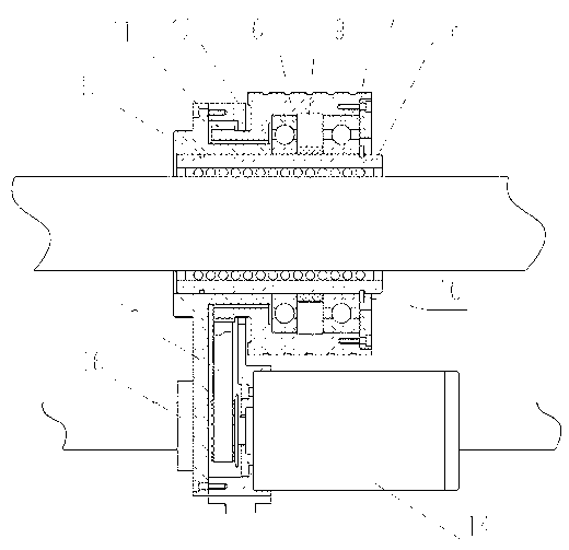
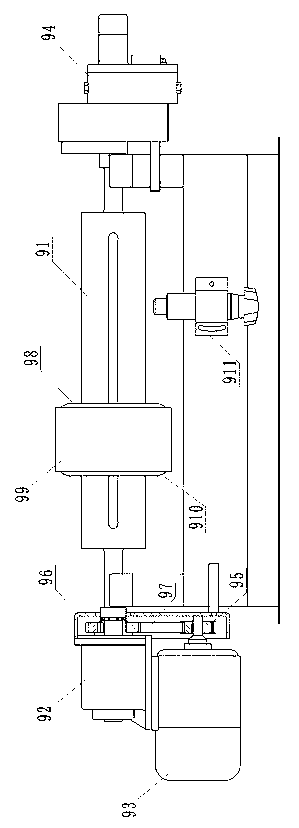
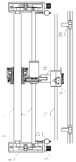
[0024] like figure 2 , image 3 As shown, they are respectively a schematic diagram of the main structure of the grinding device of the licker-in machine of the present invention, and a schematic diagram of the partially enlarged structure of the grinding head unit.

[0025] A grinding device for a licker-in machine, comprising a grinding head unit, a roller unit, and a power unit. The roller 1 and the guide rod 2 are arranged in parallel, and the two ends are respectively installed on the bottom plate of the roller seat 4 through the roller support 3; the grinding head unit includes a grinding head, a high-precision ball bearing 7, a high-precision linear bearing 8, and a linear bearing 16 , the front part of the grinding head unit is installed on the main roller 1 through a high-precision linear bearing 8, and the rear part is installed on the guide rod 2 through a linear bearing 16, and is driven by a power unit to reciprocate along the main roller 1 and the guide rod 2 ...


PUM


Abstract

The invention discloses a grinding device of a licker-in grinding and covering machine. The grinding device comprises a grinding head unit, a roller unit and a power device, wherein the roller unit comprises a main roller, a guide rod, a grinding roller support and a grinding roller seat bottom plate; the main roller is in parallel to the guide rod; both ends are respectively arranged on the grinding roller seat bottom plate through the grinding roller support; the grinding head unit comprises a grinding head, a high-precision ball bearing, a high-precision linear bearing and linear bearings; the grinding head unit is arranged on the main roller and the guide rod through the two linear bearings, and is driven by the power unit to perform reciprocating motion along the main roller and the guide rod; the grinding head is directly arranged on the high-precision ball bearing; the high-precision ball bearing is also directly arranged on the high-precision linear bearing, and is driven by the power unit so that rotary motion is performed on the grinding head by taking the main roller as an axle center. The grinding device has the beneficial effects that the equipment is high in precision during rotary motion and reciprocating motion, adjustable in stroke, smooth in reversing and extremely low in failure rate; and the whole equipment is high in grinding quality, simple in structure and convenient to operate, and is free of amending a grinding wheel during the using process.

Description

technical field [0001] The invention relates to a repair and maintenance device for a licker-in machine used in the textile industry, in particular to a grinding device for a licker-in machine. Background technique [0002] The licker-in rollers on the licker-in machine in the textile industry need to be ground timely because the licker-in rollers will wear out after use. [0003] The existing grinding device of the licker-in machine includes a grinding head unit, a roller unit, a power unit, and a grinding wheel correction unit. The grinding head unit is arranged on the roller unit, and the power unit provides power for the grinding head unit to make the grinding head The unit performs rotary motion and lateral reciprocating movement, and the grinding wheel correction unit corrects the grinding wheel of the grinding head unit. [0004] Specifically, as figure 1 As shown, the grinding head unit includes a grinding head 98, a large hole grinding wheel 99, and a grinding whe...

Claims


Application Information

Patent Timeline
Patent Type & Authority Applications(China)
IPC IPC(8): B24B5/37B24B5/35B24B47/02
Inventor 蒋柯马骏
Owner 无锡立达纺织机械器材有限公司
Why Eureka
Try Eureka