
Novel rotor of brushless direct current motor

A brushless DC motor and rotor technology, applied to electrical components, electromechanical devices, magnetic circuit rotating parts, etc., can solve the problems of increased motor vibration and noise, large starting moment of inertia, and obvious stator commutation vibration noise, etc., to achieve Effects of improving noise and vibration, reducing moment of inertia, and improving back EMF waveform

Inactive Publication Date: 2015-06-24
FOSHAN CITY NANHAI POPULA FAN
View PDF3 Cites 3 Cited by
  • Summary
  • Abstract
  • Description
  • Claims
  • Application Information

AI Technical Summary

Problems solved by technology

The main reason is that the magnetic force of the rotor is relatively strong, which makes the rotor's starting moment of inertia relatively large. When starting, it needs to apply current and torque, which increases the vibration and noise of the motor.
During operation, since the N and S poles of the magnetic force on the surface of the rotor are relatively close, the N and S poles interfere with each other significantly, resulting in obvious vibration noise of the stator commutation when the rotor rotates.

Method used


Image

  • Novel rotor of brushless direct current motor
  • Novel rotor of brushless direct current motor
  • Novel rotor of brushless direct current motor

Examples


Embodiment Construction

[0014] In order to make the present invention easier to understand, specific embodiments of the present invention will be further described below. The specific implementation of the present invention will be described in detail below in conjunction with the accompanying drawings. As a part of this specification, the principles of the present invention will be described through examples. Other aspects, features and advantages of the present invention will become clear through the detailed description. In the referenced drawings, the same reference numerals are used for the same or similar components in different drawings.

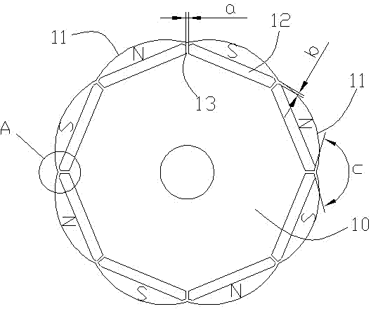
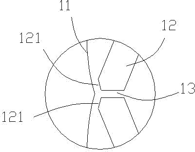
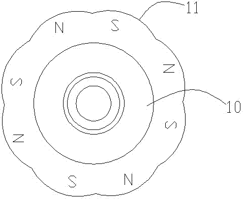
[0015] like figure 1 and figure 2 As shown, it is the new rotor of the DC brushless motor of the present invention. The new rotor of this design is an inlaid rotor, which is composed of an eccentric arc 11 and a permanent magnet slot 12. Preferably, the permanent magnet slot 12 is strip-shaped The main feature of the new rotor 10 of the brushless DC motor...


PUM


Abstract

The invention discloses a novel rotor of a brushless direct current motor. The peripheral face of the rotor is composed of an even number of eccentric arcs, the contour of the rotor is in a quincunx shape, a permanent magnet groove corresponds to each eccentric arc, a magnetism isolating bridge is arranged between every two adjacent permanent magnet grooves, and magnetic blocks are imbedded in each permanent magnet groove in sequence from N to S; the two ends of each magnetism isolating bridge are parallel, the width a of each magnetism isolating bridge is 0.3-3 mm, and the eccentric distance of each eccentric arc is 0.5-3mm; the two ends, close to an end face of the corresponding eccentric arc, of each magnetism isolating bridge are provided with oblique planes which are approximately parallel to the two ends of the corresponding eccentric arc, and the included angle c between the oblique planes on every two adjacent permanent magnet grooves ranges from 75 degrees to 160 degrees. The eccentric arcs and the permanent magnet grooves of the novel rotor are designed to be mutually matched, the air-gap magnetic field and the winding counter electromotive force wave form are improved, the magnetic field cutting inside the motor is effectively improved, and the rotation inertia moment of the rotor is decreased, so that the commutation noise and commutation vibration generated when the motor rotates are reduced, and an obvious effect for meeting the operating requirements of silence and slight vibration is achieved for the motor.

Description

technical field [0001] The invention relates to the technical field of DC brushless motors, in particular to a novel rotor of DC brushless motors. Background technique [0002] There are many kinds of motors available, which can be roughly divided into two categories: AC motors and DC motors. DC motors are further divided into brushed and brushless. AC motors have the advantages of simple structure, low cost, and low noise. Speed ​​is difficult. Although the brushed DC motor is easy to adjust the speed, it has the disadvantages of loud noise, complex structure, prone to failure, and difficult maintenance. Brushless DC motor is a representative new type of mechatronics product. The technologies involved include material technology, electronic technology, information technology and detection technology. Brushless motor is developed from micro motor. Brushless DC motor relies on its Excellent working performance has been widely used in automobiles, household appliances, aeros...

Claims


Application Information

Patent Timeline
IPC IPC(8): H02K1/27H02K29/03
Inventor 温杰泉
Owner FOSHAN CITY NANHAI POPULA FAN
Learn More