LED (Light-Emitting Diode) candle lamp

A technology of LED candle lamps and candle lamps, applied in lighting devices, cooling/heating devices of lighting devices, light sources, etc., can solve problems such as inability to guarantee life, poor projection efficiency, and increased environmental pollution, and overcome the directivity of LED lights problems, increase the light angle, and prolong the service life

Inactive Publication Date: 2012-12-19
SUZHOU JINKE XINHUI PHOTOELECTRIC TECH
View PDF3 Cites 4 Cited by
  • Summary
  • Abstract
  • Description
  • Claims
  • Application Information

AI Technical Summary

Problems solved by technology

After fluorescent lamps replace traditional tungsten bulbs, although they can produce some energy-saving effects, they are difficult to recycle, which increases environmental pollution. Therefore, LED bulbs developed in recent years have become tomorrow's lighting star
However, LED bulbs are directional light sources, and their design often cannot meet the needs of all lighting environments. For example, they cannot be directly used in crystal lighting, chandeliers, wall lamps, etc. , making LEDs into candle lights came into being
[0003] At present, there are two kinds of LED candle lamps: one uses acrylic light guide column, the disadvantage is that the projection efficiency is low, and only about 60-70% of the imported light can be projected to the required place. If multiple LEDs are used, the projection efficiency is higher. Poor; the other is to place the LED horizontally in the lamp housing. Although most of the light can be cast to the required place, the heat conduction distance between the LED and the radiator is long, the thermal resistance is too large, and the heat dissipation is poor, so it cannot be guaranteed. life

Method used


Image

  • LED (Light-Emitting Diode) candle lamp

Examples


Embodiment Construction

[0015] The present invention will be specifically introduced below in conjunction with the accompanying drawings and specific embodiments.

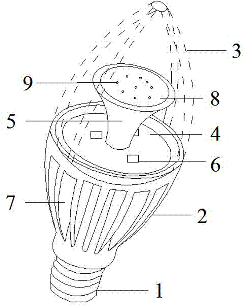
[0016] refer to figure 1 , The LED candle lamp of the present invention includes: copper head 1, radiator 2, light source fixing plate 4, reflector 5, LED light source 6, wires (not shown) and lamp housing 3. The specific structure, positional relationship and connection relationship are described as follows:

[0017] The copper head 1 is used to connect with the lamp holder (not shown), and it can be of specifications such as E12, E14, E27, etc., and there are many choices without limitation.

[0018] One end of the radiator 2 is fixedly connected with the copper head, and the other end forms an opening, and the lamp housing 3 is sleeved on the opening. The inside of the radiator 2 is formed with a cavity, which is used to accommodate the wires connected to the power supply; the side is formed with a long heat dissipation hole 7, wh...


PUM


Abstract

The invention discloses an LED (Light-Emitting Diode) candle lamp, comprising a light source fixing board and a reflector. The light source fixing board is an aluminum base board; the reflector is horn-shaped; LED light sources are distributed along the outer side of the reflector; the reflector is made of an acrylic material; a continuous arc surface plated with a silver surface is formed at the open end of the reflector; transmitting points are formed on the silver surface; and the transmitting points are formed through laser burn-off. The LED candle lamp provided by the invention has the following beneficial effects: the projection direction of light emitted by an LED light source is determined according to the height and the size of an opening of the horn-shaped reflector, so that the light-emitting angle can be enlarged, and the LED lamp light directivity problem can be overcome; and the reflector is made of acrylic material and the silver surface is plated on the arc surface, so that the light-emitting amount above the reflector is controlled by the transmitting points formed on the silver surface. Therefore, the ratio of the light-emitting amount above the reflector and the light-emitting amount at the lateral direction of the reflector can be controlled, so that the light projection direction and the light amount of the LED candle lamp can be adjusted; the reflection efficiency is high and the energy conversation can be realized; and the light source fixing board uses the aluminum base board, so that the heat dissipation effect is good, and the service life of the LED candle lamp can be prolonged.

Description

technical field [0001] The invention relates to a lamp, in particular to an LED candle lamp. Background technique [0002] Global warming has caused great damage to the earth's environment, and energy conservation and emission reduction are the responsibility of all. Since the invention of lighting lamps, tungsten filament bulbs have become the main lighting products. However, they have always had the serious disadvantages of low energy efficiency and high energy consumption. According to statistics, lighting electricity accounts for 20% of global electricity consumption. After fluorescent lamps replace traditional tungsten bulbs, although they can produce some energy-saving effects, they are difficult to recycle, which increases environmental pollution. Therefore, LED bulbs developed in recent years have become tomorrow's lighting stars. However, LED bulbs are directional light sources, and their design often cannot meet the needs of all lighting environments. For example...

Claims


Application Information

Patent Timeline
Patent Type & Authority Applications(China)
IPC IPC(8): F21S2/00F21V7/22F21V29/00F21Y101/02F21V29/83F21V29/85F21V29/89
Inventor 傅立铭
Owner SUZHOU JINKE XINHUI PHOTOELECTRIC TECH
Why Eureka
Try Eureka