LED (light-emitting diode) tunnel light adopting light housing serving as installation interface bracket structure

A technology of LED tunnel light and installation interface, which is applied to the components of lighting devices, cooling/heating devices of lighting devices, lighting devices, etc., can solve the problems of high manufacturing cost, maintenance delay, and mutual incompatibility of LED lighting products. Achieve the effect of facilitating standardized mass production, reducing metal material consumption, high versatility and interchangeability

Active Publication Date: 2012-12-19
GUIZHOU GUANGPUSEN PHOTOELECTRIC
View PDF4 Cites 3 Cited by
  • Summary
  • Abstract
  • Description
  • Claims
  • Application Information

AI Technical Summary

Problems solved by technology

This has brought a series of fatal problems such as high manufacturing cost, inconvenient use, and difficult maintenance to LED lighting products.
First of all, it is impossible to achieve national and even global unified standardized production in manufacturing, resulting in many product specifications, few batches, and high prices; secondly, the products of each company are various, not universal, let alone interchangeable; thirdly, product failure Sometimes it is necessary to remove the LED optical module, driving power supply, lamps and other assemblies as a whole for maintenance, which is extremely inconvenient to maintain, and it is very easy to cause defects such as expansion of faults, delay in maintenance, and high maintenance costs.
These defects have greatly restricted the promotion and use of LED lighting, and are flaws in the promotion of LED lighting products.

Method used


Image

  • LED (light-emitting diode) tunnel light adopting light housing serving as installation interface bracket structure
  • LED (light-emitting diode) tunnel light adopting light housing serving as installation interface bracket structure
  • LED (light-emitting diode) tunnel light adopting light housing serving as installation interface bracket structure

Examples


Embodiment 1

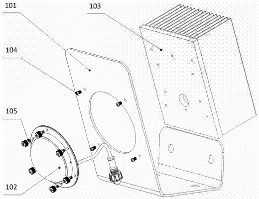
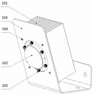
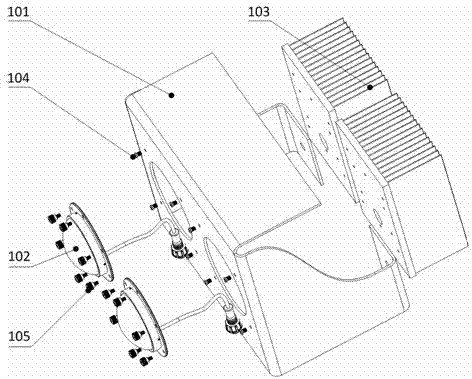
[0066] Example 1. The LED tunnel light that uses the lamp housing as the bracket structure of the installation interface, such as figure 1 with figure 2 As shown, it includes a lamp housing 101 formed by metal stamping or plastic die-casting process. The lamp housing 101 includes an installation interface bracket plate for installing an extruded heat sink 103 and an anchor screw hole for fixing and installing the entire LED tunnel lamp; The mounting interface bracket plate is provided with more than one opening for installing the extruded heat sink 103, the extruded heat sink 103 is provided with an installation interface, and the LED bulb 102 with waterproof and dustproof functions is arranged on the installation interface. The extruded heat sink 103 comprises a substrate, and one side of the substrate is provided with fins, such as Figure 25 As shown, the other side of the substrate is provided with an installation interface for installing the LED bulb 102; the inst...


PUM


Abstract

The invention discloses an LED (light-emitting diode) tunnel light adopting a light housing serving as an installation interface bracket structure. The LED tunnel light comprises a light housing (101) which is formed by punching metal or casting plastic, wherein the light housing (101) comprises an installation interface bracket plate for installing an extrusion type radiator (103), and a foundation bolt hole for fixedly installing the whole LED tunnel light; at least one opening hole for installing the extrusion type radiator (103) is arranged on the installation interface bracket plate; an installation interface is arranged on the extrusion type radiator (103); and a waterproof and dustproof LED bulb (102) is arranged on the installation interface. The LED tunnel light is simple in structure and low in cost, can be conveniently and quickly installed, used and maintained with a low cost, is hard to expand a fault, achieves the independence of the bulb of the LED light, the lights and a lighting control product on production and use, greatly reduces the links of production, achieves mass production and brings advantages to the application and the industrial scale of LED energy-saving lighting products.

Description

technical field [0001] The invention relates to an LED tunnel light, in particular to an LED tunnel light using a lamp housing as an installation interface support structure. Background technique [0002] As a new generation of lighting technology, semiconductor lighting has high photoelectric conversion rate, easy control of light source direction, easy control of lighting period and mode, high color rendering of light source, high power factor under reasonable design, etc., which cannot be compared with other existing lighting technologies. The five energy-saving advantages are favored by global investors and strongly supported by governments of various countries. The luminous efficiency of current LED lighting can exceed 70LM / W, which is more energy-saving than traditional energy-saving lamps. Theoretically, the luminous efficiency of green LEDs can be as high as 683LM / W; the theoretical efficiency of white LEDs can also reach 182.45LM / W, so there is huge room for improv...

Claims


Application Information

Patent Timeline
Patent Type & Authority Applications(China)
IPC IPC(8): F21S8/00F21V19/00F21V29/00F21W131/101F21Y101/02F21V29/71F21V29/76
Inventor 张继强张哲源
Owner GUIZHOU GUANGPUSEN PHOTOELECTRIC
Why Eureka
Try Eureka