


Quick Research
Generate reliable direction feasibility study reports for your R&D in just a few steps.

Technical Q&A
Discover and master advanced knowledge NOW. Basics, ideas, possibilities, all at once.

Find Solutions
As an expert in R&D theories, this can generate solutions to your technical problems instantly.

Evaluate Feasibility
Analyze your overall solution with one click, know your potential R&D risks in advance.

Monitor Landscape
Get weekly tech updates, stay abreast of the latest tech innovations and key insights.
Gear radial chamfer checking device
A technology of inspection devices and gears, applied in the field of physics, can solve problems such as high requirements for inspectors' experience and quality, failure to guarantee product pass rate, and lack of competitiveness of products, etc., and achieve the effect of simple structure, reasonable design, and high accuracy
- Summary
- Abstract
- Description
- Claims
- Application Information
AI Technical Summary
Problems solved by technology
Method used
Image

Examples
Embodiment 2
[0030] Such as Figure 5 As shown, the structure and principle of this embodiment are basically the same as those of the first embodiment. The difference lies in: the connecting mechanism includes a supporting block 6, a connecting rod 7, a guide sleeve 5, a limit sliding sleeve, and a return spring 11; Dial indicator 9.
[0031] More specifically, the support block 6 is fixed on the base 8, and the base 8 can improve the stability of the support block 6 placed on the work surface. The support block 6 has a through hole, and an insert block 12 is fixed on the support block 6, the measuring rod 92 of the dial indicator 9 is inserted and fixed on the insert block 12, and the probe 91 of the dial indicator 9 penetrates into the through hole. The guide sleeve 5 is tubular and one end is fixed on the support block 6, the limit sliding sleeve is located in the guide sleeve 5 and can move axially along the inner wall of the guide sleeve 5, and the other end of the guide sleeve 5 is fixe...
Embodiment 3
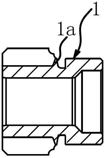
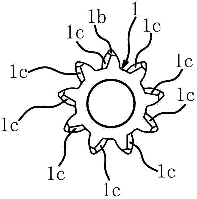
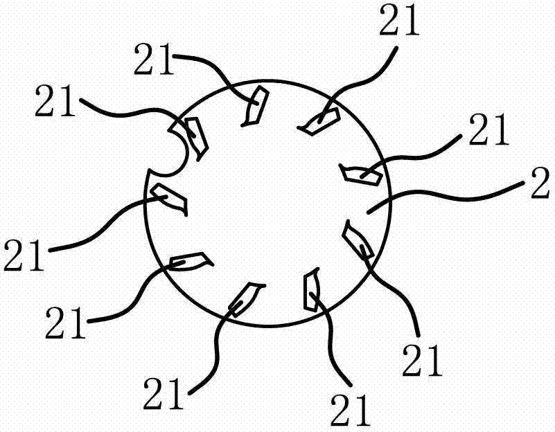
[0040] Such as Image 6 As shown, the structure and principle of this embodiment are basically the same as those of the second embodiment. The difference lies in that the limit sliding sleeve includes a body 3 and a positioning pin 14. The inner wall of the main body 3 is provided with an annular distance-limiting concave shoulder 32 which is located on the outside of the template 2. The inclined surface of the circumferential chamfer 1b of the gear to be measured 1 can abut against the bottom surface of the annular travel-limiting concave shoulder 32. The positioning pin 14 is fixed on the body 3 and the outer surface of the positioning pin 14 can abut against the tooth surface of the gear 1. The positioning pin 14 is perpendicular to the plate surface of the template 2 and the outer ends of the positioning pin 14 are located in two adjacent areas from the main body 3. The parts between the convex bodies 21 pass through.
[0041] The steps of using this inspection device to in...
PUM
 Abstract
Description
Claims
Application Information
 - R&D Engineer
- R&D Manager
- IP Professional
- Industry Leading Data Capabilities
- Powerful AI technology
- Patent DNA Extraction
Browse by: Latest US Patents, China's latest patents, Technical Efficacy Thesaurus, Application Domain, Technology Topic, Popular Technical Reports.
© 2024 PatSnap. All rights reserved.Legal|Privacy policy|Modern Slavery Act Transparency Statement|Sitemap|About US| Contact US: help@patsnap.com