Method for simultaneously measuring temperature and stress of fiber bragg gratings (obtained by corrosion) with different diameters

A fiber grating and fiber grating demodulation technology, which is applied in the measurement, thermometer, measuring device and other directions by measuring the changing force of the optical properties of the material when it is stressed, and can solve the problem of high temperature resistance, high fiber loss, demodulation scheme Complexity and other problems, to achieve the effect of low cost and overcoming cross-sensitive problems

Inactive Publication Date: 2012-12-19
NAT UNIV OF DEFENSE TECH
View PDF3 Cites 20 Cited by
  • Summary
  • Abstract
  • Description
  • Claims
  • Application Information

AI Technical Summary

Problems solved by technology

[0013] At present, the simultaneous differential measurement of temperature and stress using fiber gratings still faces a series of problems: (1) The doping concentration distribution of the fiber core is not easy to control; (2) The demodulation scheme is complex in structure, low in precision and high in cost; (3) ) Most organic packaging materials cannot be used in harsh environments (that is, not resistant to high temperature and high pressure); (4) The problem of high loss in the fusion of different diameter optical fibers

Method used


Image

  • Method for simultaneously measuring temperature and stress of fiber bragg gratings (obtained by corrosion) with different diameters
  • Method for simultaneously measuring temperature and stress of fiber bragg gratings (obtained by corrosion) with different diameters
  • Method for simultaneously measuring temperature and stress of fiber bragg gratings (obtained by corrosion) with different diameters

Examples


Embodiment Construction

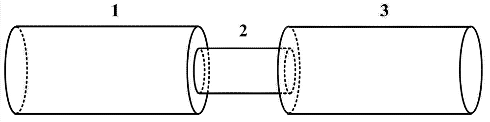
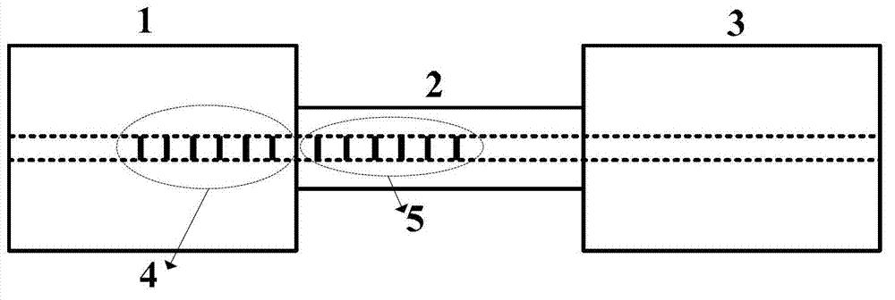
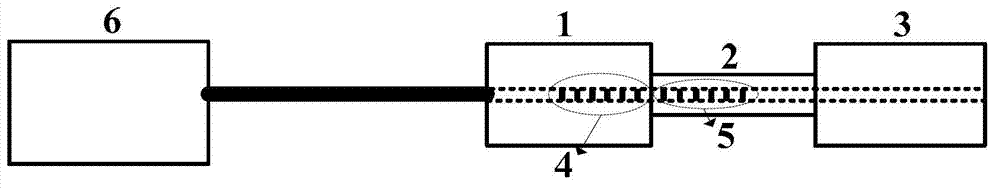
[0035] see image 3 , the device of this embodiment includes fiber gratings of different diameters obtained by etching methods, wherein 1 and 3 are ordinary uncorroded photosensitive single-mode fibers, 2 is a photosensitive single-mode fiber with a smaller diameter after corrosion, and 4 is in The grating written on the ordinary optical fiber, 5 is the grating written on the corroded optical fiber, and 6 is the fiber grating demodulator. The purpose of using two fiber gratings with different diameters is to produce fiber gratings with different stress sensitivities. Fiber Bragg grating demodulator 6 continuously scans lasers of different wavelengths to be incident on the grating produced later. When the scanned wavelength satisfies the central wavelength of the grating, the light energy of this wavelength will be reflected to the fiber Bragg grating demodulator, and the fiber Bragg grating demodulator will The retroreflected laser wavelength is recorded in real time. In thi...


PUM

PropertyMeasurementUnit
diameteraaaaaaaaaa

Abstract

The invention discloses a method for simultaneously measuring temperature and stress of fiber bragg gratings (obtained by corrosion) with different diameters. The method comprises a fiber bragg grating demodulation instrument or a device which has functions similar to those of the fiber bragg grating demodulation instrument, and the fiber bragg gratings (obtained by the corrosion) with the different diameters, wherein the fiber bragg grating demodulation instrument can be used for fast scanning lasers with different wavelengths; when the lasers with a certain length can meet reflection conditions of the central wavelengths of the fiber bragg gratings, the lasers with the certain wavelength can be sent back to the fiber bragg grating demodulation instrument and are recorded; and the fiber bragg gratings with the different diameters have different stress sensitivities and same temperature senstivity, so that two different fiber bragg gratings can generate different central wavelength drifts under a same environmental influence, two wavelength drift equations obtained by using the two fiber bragg gratings are simultaneous, namely the change conditions of the environment temperature and the stress can be respectively obtained by solving the simultaneous equations. According to the scheme, the characteristic that fiber bragg gratings with the different diameters have the different stress sensitivities is utilized, and the method is easy and feasible, is low in cost and can effectively overcome the cross sensitivity problem of the fiber bragg gratings.

Description

technical field [0001] The invention relates to a method for simultaneously measuring temperature and stress by obtaining fiber gratings with different diameters through corrosion. Background technique [0002] The rapid development of fiber optic technology makes the fiber grating sensor based on fiber grating become a hot spot in the field of sensor research. At present, more studies at home and abroad are on the fiber grating written in ordinary photosensitive single-mode fiber. This kind of fiber grating has the problem of temperature and stress cross-sensitivity that is difficult to eliminate in practical applications, which seriously affects the transmission of fiber grating. sensory applications. [0003] According to the optical coupling mode theory, the central reflection wavelength of the fiber grating is: [0004] lambda B =2n eff Λ (1) [0005] Among them, n eff Represents the effective refractive index of the optical field transmission mode in the fiber, a...

Claims


Application Information

Patent Timeline
Patent Type & Authority Applications(China)
IPC IPC(8): G01K11/32G01L1/24G01K11/3206
Inventor 宋章启卫正统张学亮阳明晔陈宇中孟州
Owner NAT UNIV OF DEFENSE TECH
Why Eureka
Try Eureka