Multi-functional mechanical property tester of rock
A technology of rock mechanics and testing machine, applied in the direction of testing material strength by applying stable bending force, testing material strength by applying stable shear force, testing material strength by applying stable tension/pressure, etc., can solve the problem of loading machine The unreasonable design of the frame structure makes it impossible to test and test, and the use efficiency of the testing machine is low, so as to achieve the effects of reasonable force, increased rigidity, convenient installation and safety.
- Summary
- Abstract
- Description
- Claims
- Application Information
AI Technical Summary
Problems solved by technology
Method used
Image
Examples
Embodiment 1
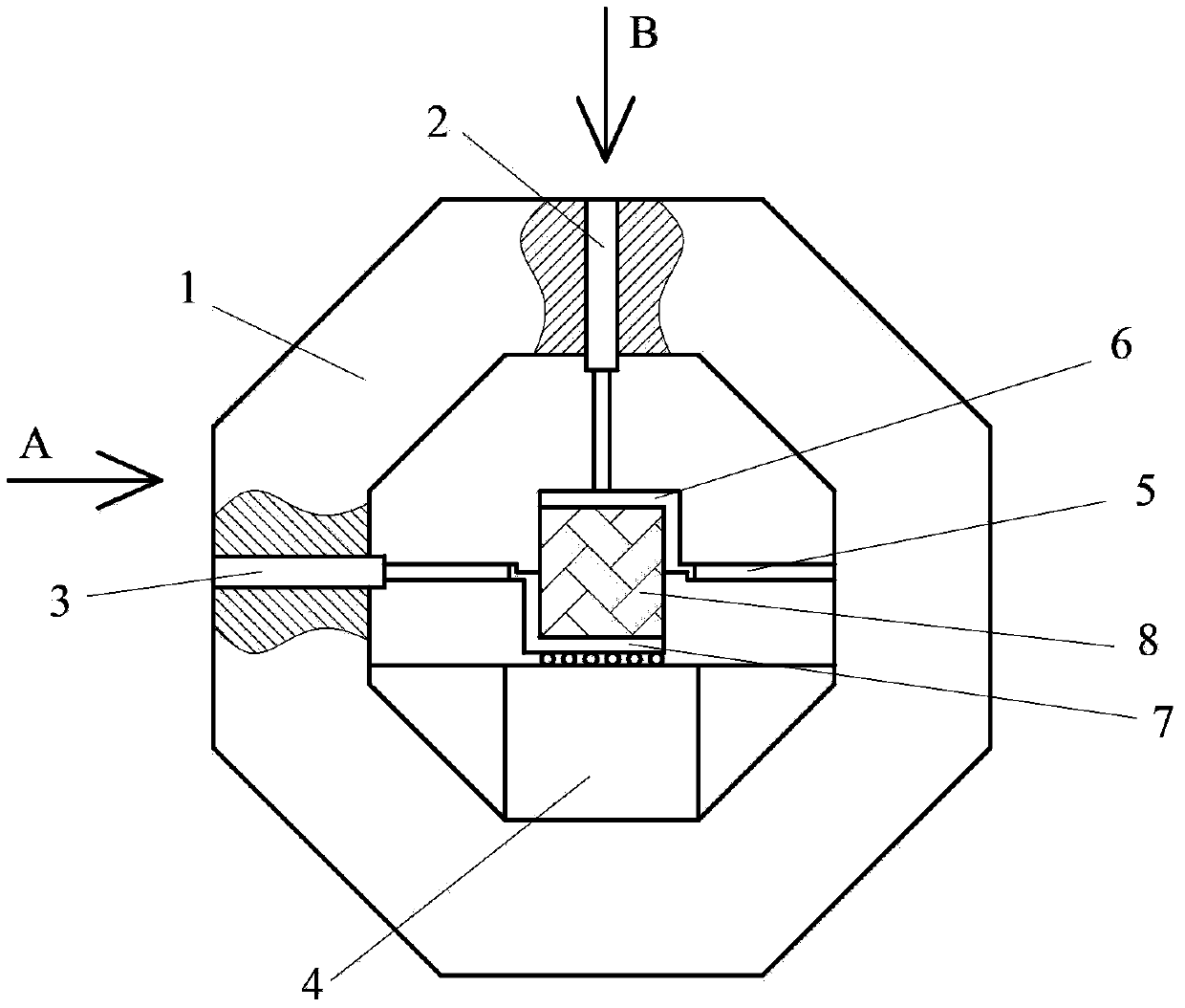
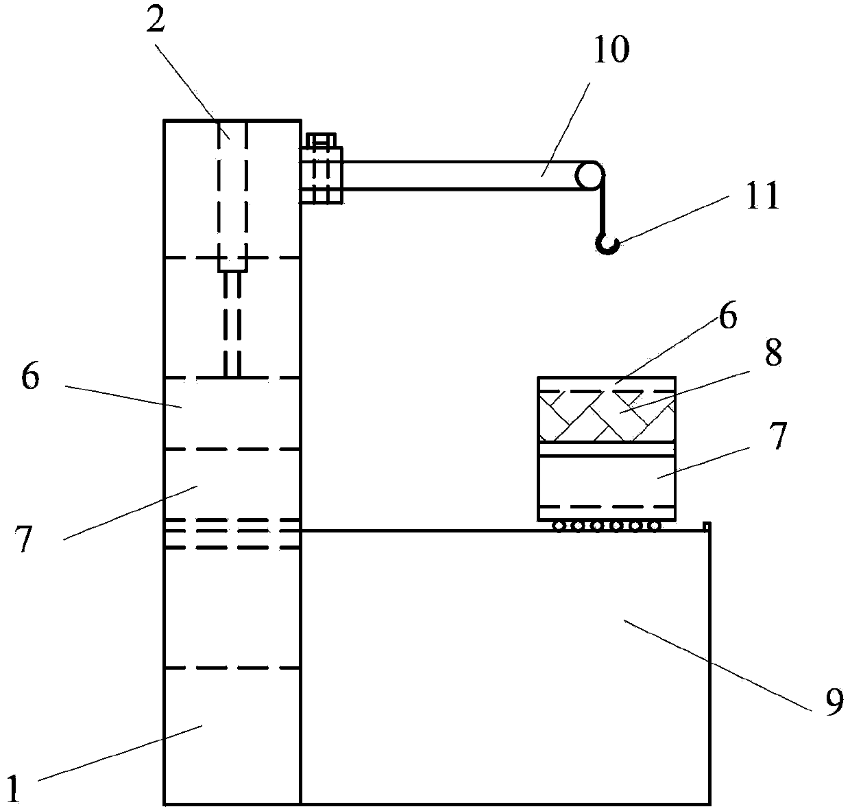
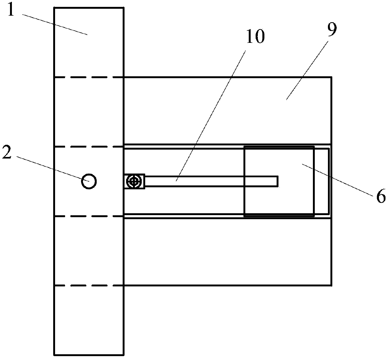
[0023] The multifunctional rock mechanics testing machine of this embodiment has a structure as attached figure 1 , 2 As shown in and 3, its composition includes an eight-sided annular integral loading frame 1, which is placed on the bottom wall of the annular inner wall of the loading frame for carrying the bearing base 4 of the rock test piece 8, and is used to improve the distribution of the shear load. The upper shear box 6 connected to the upper part of the rock test piece and the lower shear box 7 enclosing the lower part of the rock test piece are arranged on the top wall of the annular inner wall of the loading frame and act vertically downward on the rock test piece placed on the bearing base 4. The rock test piece is fixed in the first actuator 2 in the loading frame, and the second actuator 3 that acts on the rock test piece horizontally on the vertical wall surface of the annular inner wall of the loading frame is arranged on the loading frame. On the vertical wal...
Embodiment 2
[0026] attached Figure 4It is a schematic diagram of implementing a uniaxial compression test on a rock specimen by using the multifunctional rock mechanical performance testing machine of the present invention. The structure of the testing machine is basically the same as that of Example 1, except that the second actuator 3 is shrunk to the loading frame during the test In the body, the passively loaded support rod 5, the upper shear box 6 and the lower shear box 7 were removed, and the rock specimen for the uniaxial compression test was placed between the first actuator 2 and the bearing base 4, and the A lower bearing plate 13 is placed between the test piece 8 and the bearing base 4 , and an upper bearing plate 12 is placed between the rock test piece 8 and the first actuator 2 . The test is carried out by applying a compression load by the first actuator 2, so as to measure the mechanical properties of the rock specimen against uniaxial compression.
Embodiment 3
[0028] attached Figure 5 It is a schematic diagram of implementing a uniaxial tensile test on a rock specimen by using the multifunctional rock mechanical performance testing machine of the present invention. The structure of the testing machine is basically the same as that of Example 1, except that the second actuator 3 is shrunk to the loading machine during the test process. Inside the frame, remove the passively loaded support rod 5, the upper shear box 6 and the lower shear box 7, and the rock specimen for the uniaxial tensile test is connected to the first actuator 2 through the upper tension device 14, and the The extension device 15 is connected with the load-bearing base 4 fixed on the loading frame, and the tensile load is applied by the first actuator 2 to carry out the test, so as to measure the mechanical properties of the rock specimen against uniaxial tension.
PUM
 Abstract
Description
Claims
Application Information
 - R&D
- Intellectual Property
- Life Sciences
- Materials
- Tech Scout
- Unparalleled Data Quality
- Higher Quality Content
- 60% Fewer Hallucinations
Browse by: Latest US Patents, China's latest patents, Technical Efficacy Thesaurus, Application Domain, Technology Topic, Popular Technical Reports.
© 2025 PatSnap. All rights reserved.Legal|Privacy policy|Modern Slavery Act Transparency Statement|Sitemap|About US| Contact US: help@patsnap.com


