
Optical connector

A technology for optical connectors and interconnections, applied in light guides, optics, instruments, etc., can solve problems such as troublesome cleaning, impossible to avoid abrasive powder, and increased connection loss

Active Publication Date: 2012-12-19
JAPAN AVIATION ELECTRONICS IND LTD
View PDF10 Cites 5 Cited by
  • Summary
  • Abstract
  • Description
  • Claims
  • Application Information

AI Technical Summary

Problems solved by technology

[0019] However, Patent Document 1 does not mention that abrasion powder is generated when the guide pin is inserted and fitted into the guide hole. Furthermore, Patent Document 1 uses guide pins and guide holes based on JIS standards, so it is impossible to avoid repetitions. Generation of abrasive powder caused by assembly and disassembly
[0020] In order to avoid the increase of the connection loss caused by the generation of the abrasion powder, for example, the end face of the ferrule needs to be cleaned frequently, but frequent cleaning is troublesome.
Moreover, the above-mentioned frequent cleaning itself is not suitable for civilian use, that is, optical connectors used by ordinary people, and it is difficult to incorporate cleaning into the conditions of use.

Method used


Image

  • Optical connector
  • Optical connector
  • Optical connector

Examples


Embodiment Construction

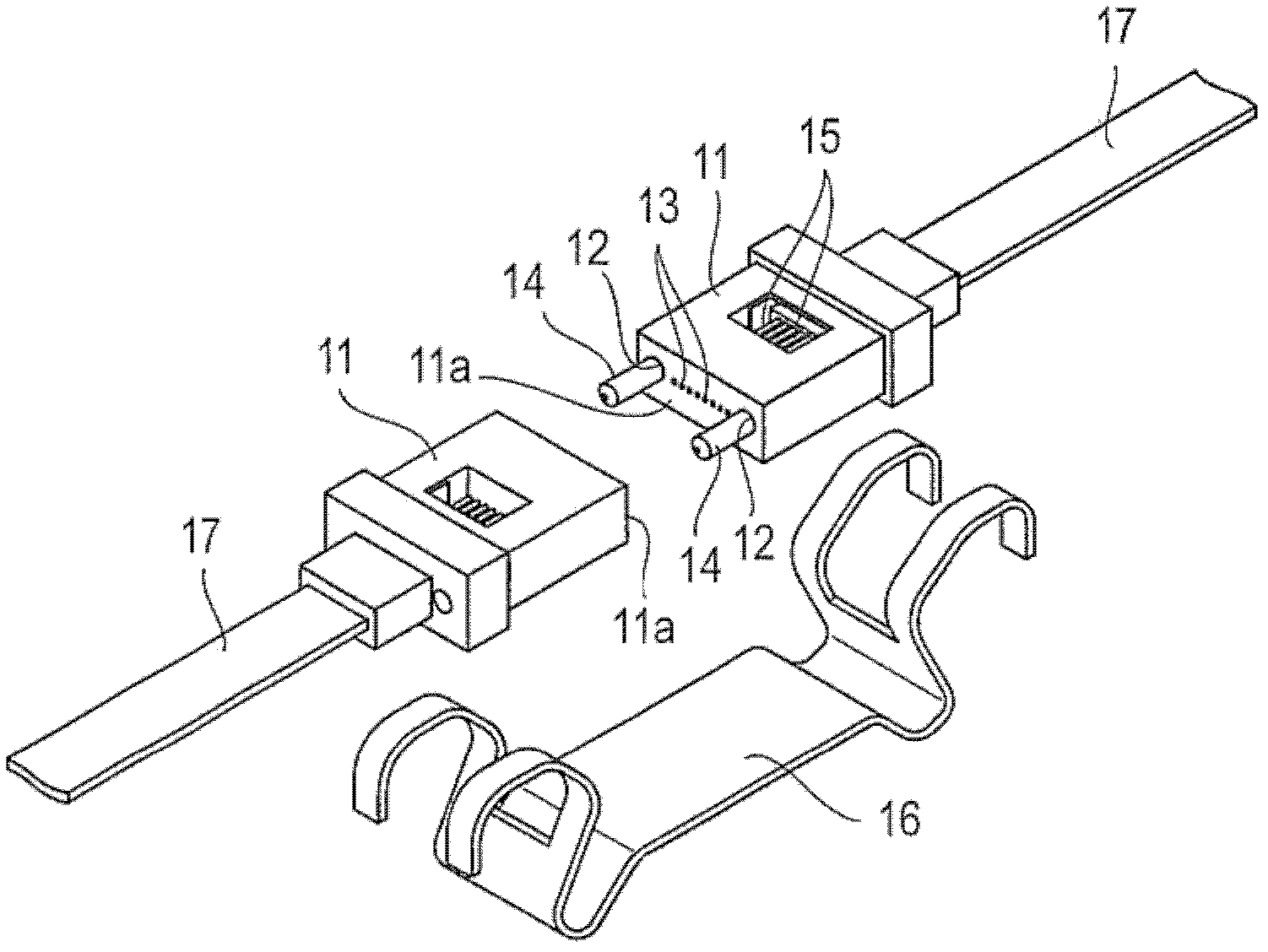
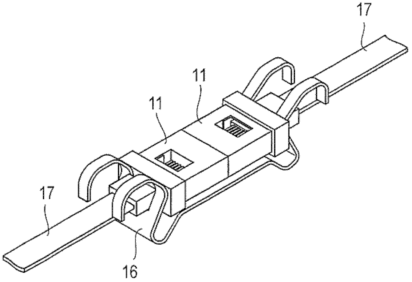
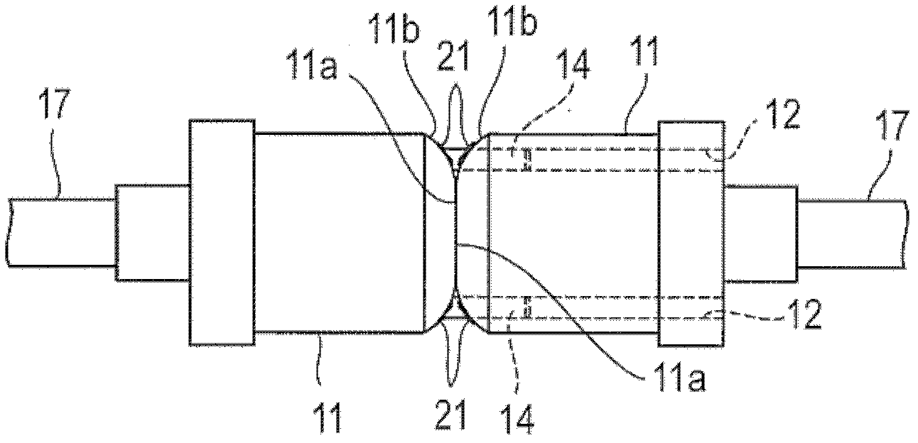
[0032] The optical connector of the present invention has, for example, the above-mentioned Figure 1A , Figure 1B In the structure of the MT-shaped optical connector shown, the end faces of the ferrules that meet each other are obliquely ground, and the gap between the guide hole that fits the guide pin and the guide pin is larger than the conventional one. The structure of the MT-shaped optical connector is: the end faces of a pair of ferrules holding a plurality of multimode optical fibers (core diameter 50 μm) are positioned by two guide pins and connected to each other, so that the optical fibers of the pair of ferrules are connected to each other .

[0033] In the following, an MT-shaped optical connector is taken as an example for description.

[0034] Figure 4 It shows that the end surfaces 11a of a pair of ferrules 11 of the MT optical connector are obliquely ground respectively, and the end surfaces 11a are positioned by guide pins 14 and connected to each other....


PUM


Abstract

In an optical connector, end faces (11a) of a pair of ferrules (11) that hold multiple optical fibers (15) are positioned with two guide pins (14) and butted against each other to connect the optical fibers in the pair of ferrules. The optical connector is provided with an urging member for pushing the end faces (11a) against each other. The end faces (11a) are ground at an angle. The gap between the guide pins (14) and guide holes (12), which open at the end faces (11a) and into which the guide pins (14) are fitted, is larger than 0.004 mm and smaller than or equal to 0.008 mm. Powder caused by the friction generated when the guide pins (14) are inserted and fitted into the guide holes (12) is greatly reduced. Connection loss does not increase even when frequent connection and disconnection are performed, and cleaning the connector becomes unnecessary.

Description

technical field [0001] The present invention relates to an optical connector, and more particularly to an optical connector employing a positioning method using guide pins such as MT-shaped optical connectors specified in JIS C 5981. Background technique [0002] The MT-shaped optical connector specified in JIS C 5981 uses a positioning method using guide pins to precisely position and connect. Figure 1A Shown is the structure of the MT-shaped optical connector. The ferrule 11 has a pair of guide holes 12 opened on its end surface 11 a and an optical fiber hole 13 between the pair of guide holes 12 . [0003] A pair of guide pins 14 are inserted and fitted into the guide holes 12 of the ferrule 11, and as Figure 1A As shown, it protrudes from the end surface 11a. By inserting and fitting the protruding guide pin 14 into the guide hole 12 of the other ferrule 11, and abutting the end surfaces 11a of the pair of ferrules 11, it can be accommodated in the fiber hole 13 and pr...

Claims


Application Information

Patent Timeline
Patent Type & Authority Applications(China)
IPC IPC(8): G02B6/38
CPCG02B6/38G02B6/3882G02B6/40G02B6/3885
Inventor 是枝雄一片木山直干滑川嘉一黑泽芳宣小岛正嗣
Owner JAPAN AVIATION ELECTRONICS IND LTD
Learn More