Array antenna second harmonic interference field modeling and calculating method

A second harmonic and array antenna technology, applied in the field of modeling and calculation of the second harmonic radiation field of an array antenna, can solve problems such as burning and performance degradation of interfered equipment, so as to suppress harmonic interference and improve anti-interference. performance effect

Active Publication Date: 2012-12-19
CHINA SHIP DEV & DESIGN CENT
View PDF5 Cites 2 Cited by
  • Summary
  • Abstract
  • Description
  • Claims
  • Application Information

AI Technical Summary

Problems solved by technology

[0003] Various forms of interference, including co-channel interference, harmonic interference, and sidelobe interference, degrade the performance of the interfered device or even burn it

Method used


Image

  • Array antenna second harmonic interference field modeling and calculating method
  • Array antenna second harmonic interference field modeling and calculating method
  • Array antenna second harmonic interference field modeling and calculating method

Examples


Embodiment Construction

[0033] The following is a specific embodiment of the present invention.

[0034] 1) Use a voltage source to feed each element of the array antenna;

[0035] 2) Set the excitation amplitude and phase of each array element;

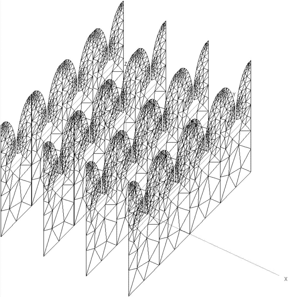
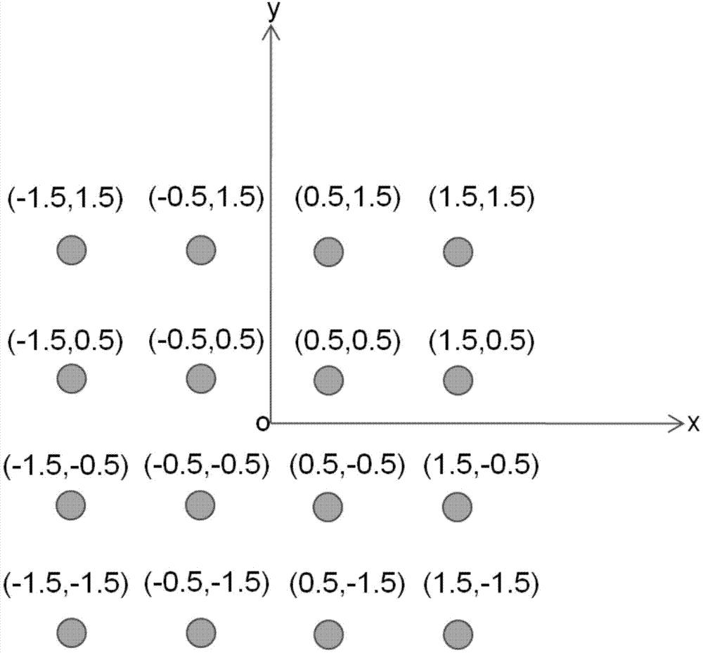
[0036] like figure 1 As shown, the array antenna composed of 16 array elements is located in the xoy plane, and the axis is the z-axis.

[0037] Among them, when the main frequency of the array antenna is transmitted (frequency is f), it is applied on the label of The amplitude and phase of the excitation voltage source at the midpoint of the array element feeder are:

[0038]

[0039] in represents the excitation voltage amplitude, j is a complex number, j 2 =-1;

[0040] φ pq For the phase of each array element:

[0041]

[0042] (p,q) is the label of each array element; dx is the spacing of the array element along the x direction, and dy is the spacing of the array element along the y direction. The phase velocities are:

[0043]

...


PUM


Abstract

The invention relates to an array antenna second harmonic interference field modeling and calculating method which includes steps of feeding for each array element of an array antenna through a voltage source; setting excitation amplitude and phase of each array element; calculating the excitation amplitude and the phase of each array element during transmission of the array antenna second harmonic according to non-linear response of amplifiers; splitting the surface of each array element triangularly and splitting a feeder linearly so as to acquire geometrical information of the surface of each array element and the feeder; and calculating induction current of the surface of each array element and the feeder according to the excitation amplitude and the phase of each array element during transmission of the array antenna second harmonic and the geometrical information of the surface of each array element and the feeder. By the array antenna second harmonic interference field modeling and calculating method, an interference field at interfered equipment during transmission of the array antenna second harmonic is acquired accurately, and then coupling level of a receiving end of the interfered equipment is acquired, so that support for suppressing and analyzing harmonic interference and improving interference resistance performance of sensitive equipment is offered.

Description

technical field [0001] The patent of the invention belongs to the field of electromagnetic compatibility, and relates to a method for modeling and calculating the second harmonic radiation field of an array antenna. Background technique [0002] With the maturity of monolithic microwave integrated circuits, broadband active array antennas are widely used in spaceborne and other platforms. The amplifier is the key component of the active array antenna. It is located behind the antenna radiating unit. When working at the main frequency, unwanted harmonics are generated due to nonlinearity, and are radiated through the antenna unit to generate other antennas and equipment on the platform. Second, third and above harmonic interference. [0003] Various interference forms, including co-channel interference, harmonic interference, and side lobe interference, reduce the performance of the interfered equipment or even burn it. In order to obtain the coupling level at the receiving...

Claims


Application Information

Patent Timeline
Patent Type & Authority Applications(China)
IPC IPC(8): G06F17/50
Inventor 温定娥吴楠谢大刚王春黄明亮
Owner CHINA SHIP DEV & DESIGN CENT
Why Eureka
Try Eureka