High voltage cable deicing device

A technology of high-voltage cables and deicing vehicles, which is applied in the installation of cables, electrical components, overhead installations, etc. It can solve the problems of cable power failure and affecting the power supply of the power system, and achieve the effect of realizing safe operation and ensuring stability

Inactive Publication Date: 2015-08-26
STATE GRID HEILONGJIANG ELECTRIC POWER CO LTD HARBIN POWER SUPPLY CO +1
View PDF7 Cites 0 Cited by
  • Summary
  • Abstract
  • Description
  • Claims
  • Application Information

AI Technical Summary

Problems solved by technology

[0006] In order to solve the problem that the existing deicing method needs to cut off the power of the cables in the deicing area, thereby affecting the power supply of the power system, the present invention designs a high-voltage cable deicing device

Method used


Image

  • High voltage cable deicing device
  • High voltage cable deicing device
  • High voltage cable deicing device

Examples


specific Embodiment approach 1

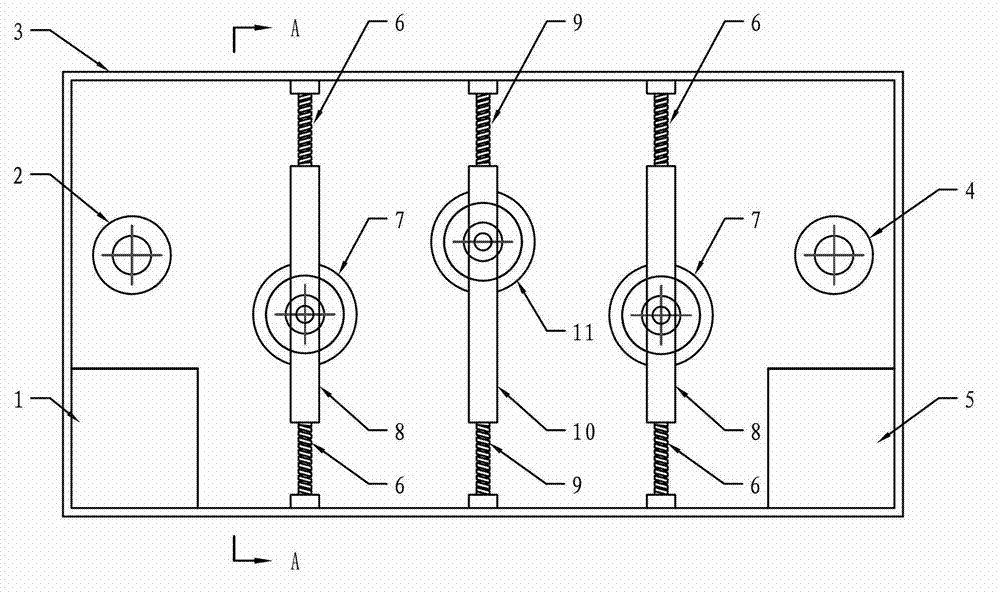
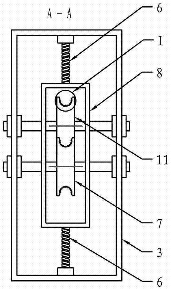
[0024] Specific Embodiment 1: The high-voltage cable deicing device described in this embodiment includes a deicing vehicle and a remote control, and the deicing vehicle includes a frame 3, an electric control box 1, a counterweight box 5, driving wheels 2, and a driven walking wheel. 4 and 3 deicing units, the driving wheel 2 and the driven wheel 4 are located at the same level and fixed on the front and rear of the frame 3 respectively, and the electric control box 1 and the counterweight box 5 are symmetrically arranged on the At the front and rear ends of the inner bottom of the frame 3, a counterweight is arranged in the counterweight box 5 so that the weight of the counterweight box 5 is the same as that of the electric control box 1, and the three deicing units are equally spaced between the active road wheel 2 and the secondary Between the moving wheels 4, the three deicing units include a pressing wheel unit and two lifting units, and the one pressing wheel unit is loc...

specific Embodiment approach 2

[0030] Embodiment 2: This embodiment is a further limitation of the high-voltage cable deicing device described in Embodiment 1. The rims of the driving wheel 2 and the driven wheel 4 described in this embodiment have grooves , for embedding high voltage cables.

[0031] The rims of the two road wheels in this embodiment are similar to the edges of train wheels, and this structure can make the two road wheels hang on the high-voltage cable stably and run smoothly.

specific Embodiment approach 3

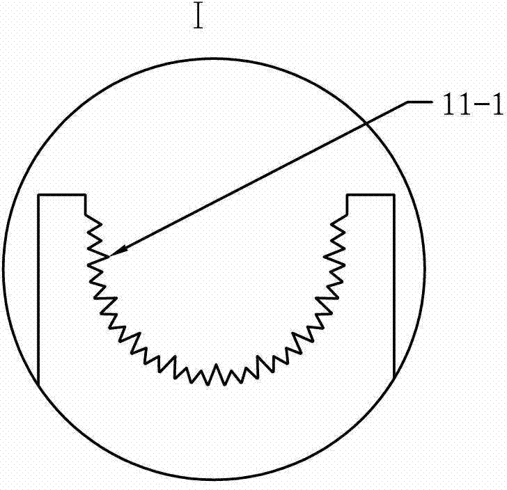
[0032]Embodiment 3: This embodiment is a further limitation to the high-voltage cable deicing device described in Embodiment 1 or Embodiment 2. The edge of the pressure roller 11 described in this embodiment has a groove, and the groove For embedding high voltage cables.


PUM


Abstract

The invention relates to power system maintaining equipment, and particularly relates to a high-voltage cable deicing device. According to the high-voltage cable deicing device, a deicing vehicle is hung on a cable through two walking wheels; a framework of the deicing vehicle is internally provided with a weight box so as to guarantee that the gravity center of the deicing vehicle is located at the center of the framework; three deicing units in the deicing vehicle are distributed between a driving walking wheel and a driven walking wheel at equal intervals, and one pressing wheel unit is placed between two hoisting units; a control circuit in a remote controller can realize data interaction through a wireless signal receiving-transmitting circuit, a wireless signal receiving-transmitting circuit in an electric cabinet and a deicing vehicle control circuit; the deicing vehicle control circuit outputs a motor control signal to a motor driving circuit which is used for driving a motor to rotate; and the motor is used for driving the driving walking wheel to rotate. The high-voltage cable deicing device disclosed by the invention controls the deicing vehicle hung on the cable to be deiced in a remote control manner so as to realize remote control work. The high-voltage cable deicing device is applicable to deicing the high-voltage cable.

Description

technical field [0001] The invention relates to power system maintenance equipment, in particular to a high-voltage wire deicing device. Background technique [0002] In the northern part of our country, the temperature is low in winter, and ice, snow or freezing rain often occur. In recent years, with the change of global climate, rainy snow and winter rain have also appeared in the southern part of our country. Under this weather environment, It will cause the surface layer of the high-voltage cable used for power transmission to freeze. When the thickness of the ice on the surface of the cable exceeds the design standard, it will cause the cable to withstand excessive pressure, which will lead to serious accidents such as pulling down the high-voltage transmission pole, and then interrupt the power supply. . [0003] Most of the existing high-voltage transmission lines are laid in the wild with inaccessible and harsh geographical environment, which leads to the problem o...

Claims


Application Information

Patent Timeline
Patent Type & Authority Patents(China)
IPC IPC(8): H02G7/16
Inventor 刘兴华刘鲁嘉刘金龙
Owner STATE GRID HEILONGJIANG ELECTRIC POWER CO LTD HARBIN POWER SUPPLY CO
Why Eureka
Try Eureka