Method of producing film by inkjet process, and film
A process and liquid technology, applied in the field of film production by inkjet process, can solve problems such as no mention, and achieve the effect of preventing ink bleeding
- Summary
- Abstract
- Description
- Claims
- Application Information
AI Technical Summary
Problems solved by technology
Method used
Image

Examples
Embodiment 1
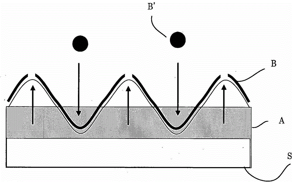
[0272] Liquid A-1 was applied on a glass slide by coating so as to form a layer with a thickness of about 15 μm. Subsequently, using the above-mentioned apparatus for spraying, the liquid B-1 was sprayed on the liquid surface of the liquid A-1 under the following conditions.
[0273] —Spray Conditions—
[0274] Resolution: 150dpi (for X-axis direction), 150dpi (for Y-axis direction)
[0275] ·Line-type one-scan printing by nozzles on one line.
[0276] Heat to 40°C and spray liquid B-1. The size of one droplet was adjusted to 7 pL, and the ejection velocity of the droplet was set at 7 m / sec.
[0277] Subsequently, curing was performed by applying light when 70 milliseconds elapsed after the liquid B-1 was sprayed, using a metal halide lamp and a device provided at the rear in the uniaxial direction. The print head advance speed was set at 500 mm / sec and the jetting frequency was set at 2.9 kHz. The amount of light applied was set to be sufficient to cure Liquids A-1 and B-1...
Embodiment 2
[0306] Liquid ejection was performed in the same manner as in Example 1, except that Liquid B-3 was used instead of Liquid B-1.
[0307] As a result, a film having a grid pattern was obtained. The results obtained when varying the layer thickness formed by Liquid A-1 and varying the elapsed time after spraying Liquid B until application of light for curing are shown in Figure 2C (photograph taken through a laser microscope). The horizontal axis represents thickness, and the vertical axis represents time.
[0308] Figure 2C It was shown that the pattern according to (1) can be obtained when the curing is performed within 68 msec after the liquid B is sprayed, and the pattern according to (3) can be obtained when the curing is performed 342 msec after the liquid B is sprayed. This indicates that in order to increase the periodic amplitude based on trigonometric functions, the layer thickness and solidification moment of Liquid B should be adapted, although this increase als...
Embodiment 3
[0314] The liquids were sprayed in the same manner as in Example 1, except that Liquid A-5 was used instead of Liquid A-1 and Liquid B-3 was used instead of Liquid B-1.
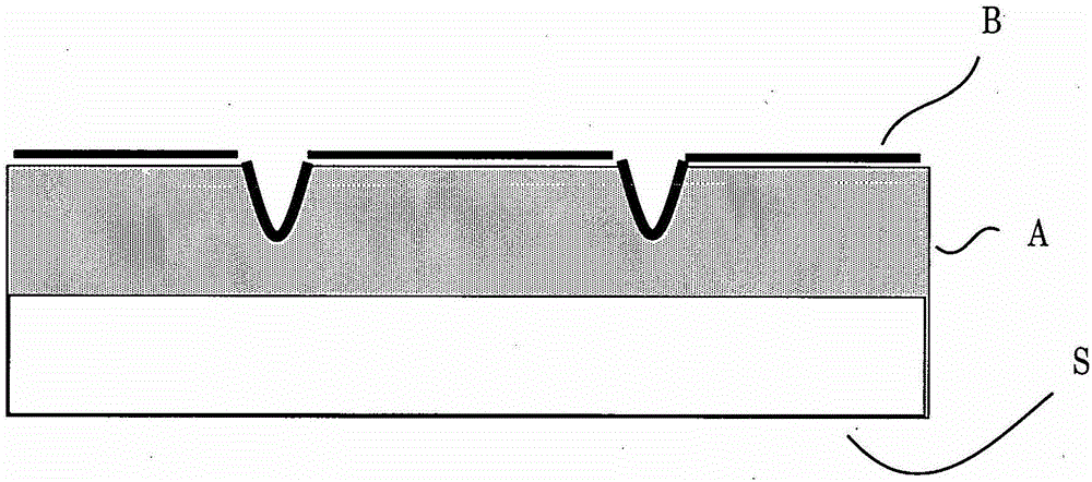
[0315] This example features high viscosity Liquid A-5. Figure 3B A photo of a film taken by a laser microscope is shown in the case where the layer thickness of Liquid A-1 is about 10 μm and the curing takes place at 350 msec after spraying of Liquid B-3; here, a regular grid pattern without A disturbed film that looks as if it was formed by drawing a line with a ruler.
[0316] Three-dimensional images of the aforementioned photographs (with no difference in scale between x, y, and z) revealed the formation of undisturbed periodic depressions (about 20 μm to about 30 μm in height), as Figure 3C and 3D shown in . Figure 3D will be Figure 3C The vertical length of the image is magnified five times. Note that in some cases, raised bumps are visible in the recesses.
[0317] When 70 milliseconds have ...
PUM
| Property | Measurement | Unit |
|---|---|---|
| viscosity | aaaaa | aaaaa |
| viscosity | aaaaa | aaaaa |
| viscosity | aaaaa | aaaaa |
Abstract
Description
Claims
Application Information
 - R&D Engineer
- R&D Manager
- IP Professional
- Industry Leading Data Capabilities
- Powerful AI technology
- Patent DNA Extraction
Browse by: Latest US Patents, China's latest patents, Technical Efficacy Thesaurus, Application Domain, Technology Topic.
© 2024 PatSnap. All rights reserved.Legal|Privacy policy|Modern Slavery Act Transparency Statement|Sitemap