Efficient vacuum cleaning machine

A vacuum cleaning machine and high-efficiency technology, applied in the field of cleaning machines, can solve the problems of reduced cleaning effect, difficult to control cleaning quality, difficult to develop ultrasonic cavitation effect, etc. Effect

Active Publication Date: 2022-02-08
上海先予工业自动化设备有限公司
View PDF8 Cites 0 Cited by
  • Summary
  • Abstract
  • Description
  • Claims
  • Application Information

AI Technical Summary

Problems solved by technology

There are two main reasons for the need for vacuum treatment. One is that the residual gas in the cleaning agent is more, and the gas content is 8-10 times that of water. The high frequency wave emitted by the ultrasonic vibrator will attenuate when it encounters gas. Ultrasonic cavitation effect is also difficult to develop under certain conditions
[0003] Existing vacuum cleaning machines are usually equipped with multiple cleaning chambers, and the cleaning liquid in each cleaning chamber can be recycled after being processed by a distillation recovery mechanism after use. During the cleaning process, impurities such as iron filings will be peeled off and float in the cleaning solution. As the cleaning process progresses, the impurity content in the cleaning solution will gradually increase, and the cleaning effect will gradually decrease with the increase in the use of the cleaning solution. It is difficult to control the cleaning quality

Method used


Image

  • Efficient vacuum cleaning machine
  • Efficient vacuum cleaning machine
  • Efficient vacuum cleaning machine

Examples


Embodiment

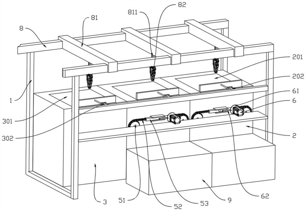
[0054] A high-efficiency vacuum cleaner, such as figure 1 Shown includes a frame 1 on which at least one first cleaning chamber 2 and a second cleaning chamber 3 are fixedly connected, and the second cleaning chamber 3 is arranged on the same side of each first cleaning chamber 2 . Each first cleaning chamber 2 and the second cleaning chamber 3 are horizontally arranged, and the top of the first cleaning chamber 2 is slidably connected with a first hatch 201 for opening or closing the first cleaning chamber 2, and the first hatch 201 is provided with There is a first driving member 202 for driving the first cabin door 201 to slide relative to the first cleaning chamber 2 . The top of the second cleaning chamber 3 is slidably connected with a second hatch 301 for opening or closing the second cleaning chamber 3 , and the second hatch 301 is provided with a door for driving the second hatch 301 to slide correspondingly to the second cleaning chamber 3 . The second driver 302 . ...


PUM


Abstract

The invention relates to the technical field of cleaning machines, and discloses an efficient vacuum cleaning machine which comprises at least one first cleaning chamber and a second cleaning chamber, wherein the second cleaning chamber is arranged on the same side of each first cleaning chamber, an injection opening is formed in the second cleaning chamber, and the injection opening is used for introducing cleaning liquid into the second cleaning chamber. The vacuum cleaning machine further comprises a moving mechanism, a filtering mechanism and a circulating mechanism, wherein the moving mechanism is used for driving a workpiece to sequentially pass through the first cleaning chambers and the second cleaning chamber, the filtering mechanism comprises at least one filtering piece, each filtering piece is used for filtering impurities in one first cleaning chamber, each filtering piece completes filtering by means of the process that the liquid level of the cleaning liquid in the corresponding first cleaning chamber is lowered, the pore spaces of the filtering holes of the filtering pieces are sequentially reduced in the direction close to the second cleaning chamber, and the circulating mechanism is used for lowering or raising the liquid level in the first cleaning chamber or the second cleaning chamber to complete filtering. The efficient vacuum cleaning machine has the characteristic that the cleaning quality is convenient to control.

Description

technical field [0001] The invention relates to the technical field of cleaning machines, in particular to a high-efficiency vacuum cleaning machine. Background technique [0002] Vacuum cleaning machine is a kind of cleaning equipment for cleaning precision industrial parts, which uses ultrasonic waves to clean the surface of workpieces. When using, it is necessary to inject cleaning liquid into the cleaning tank, and immerse the cleaning basket where the workpiece to be cleaned is placed in the cleaning liquid. After vacuuming, the power ultrasonic sound energy is converted into mechanical vibration through the transducer, and passed The wall of the cleaning tank radiates ultrasonic waves into the cleaning solution, and uses the cleaning solution to vibrate to complete the cleaning process. There are two main reasons for the need for vacuum treatment. One is that the residual gas in the cleaning agent is more, and the gas content is 8-10 times that of water. The high freq...

Claims


Application Information

Patent Timeline
Patent Type & Authority Applications(China)
IPC IPC(8): B08B3/12B08B3/08B08B3/14B08B13/00
CPCB08B3/12B08B3/08B08B3/14B08B13/00
Inventor 魏林旭
Owner 上海先予工业自动化设备有限公司
Why Eureka
Try Eureka