Dynamic inertia regulation

一种调节装置、惯性矩的技术,应用在发动机、发动机元件、风力发动机等方向,能够解决一次调节功率劣化等问题

Active Publication Date: 2012-12-19
SIEMENS GAMESA RENEWABLE ENERGY SERVICE GMBH
View PDF4 Cites 7 Cited by
  • Summary
  • Abstract
  • Description
  • Claims
  • Application Information

AI Technical Summary

Problems solved by technology

This brings its own disadvantages, namely, in non-fixed wind conditions, as they are often encountered in practice, the provision of degradation of the regulation power is only achieved once

Method used


Image

  • Dynamic inertia regulation
  • Dynamic inertia regulation
  • Dynamic inertia regulation

Examples


Embodiment Construction

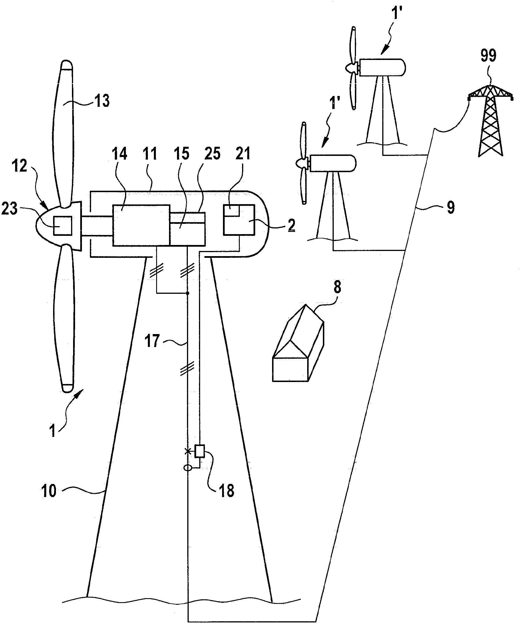
[0035] According to an embodiment of the invention, the wind energy installation 1 is conventionally constructed in terms of its basic characteristics. The wind power plant should include a tower 10, and a nacelle 11 is arranged at its upper end so as to be rotatable in the yaw direction. A wind turbine rotor 12 is rotatably arranged on the front of the wind energy equipment, and the wind turbine rotor is equipped with a plurality of rotor blades 13 whose installation angles are adjustable. In order to adjust the installation angle, a pitch adjusting device 23 is provided. The wind turbine rotor 12 drives the generator 14 via a rotor shaft. The generator, together with the converter 15 connected to it, generates electrical energy. The generator 14 is preferably implemented as a doubly-fed asynchronous generator, the stator of which is directly connected to a wire for deriving electrical energy, wherein the wire is further connected to a converter 15 which is in turn connected...


PUM


Abstract

The invention relates to a wind energy installation having a wind rotor (12), a generator (14) which is driven thereby and interacts with a converter (15) in order to produce electrical power, rotation-speed regulation (21) and converter control (25) which interacts therewith, wherein the rotation-speed regulation (21) outputs a nominal rotation speed signal (nref). Furthermore, additional regulation (3) is provided, which has an input (31) for an additional power and is designed to produce a rotation speed change signal therefrom, taking account of a rotator inertia moment, and to output this as an output signal, which is added to the nominal rotation speed signal via a logic element (29). Kinetic energy is taken from the wind rotor in a controlled manner by reducing the rotation speed and is converted by the generator (14) to additional electrical energy. This allows primary regulation power to be made available deliberately by rotation speed variation, to be precise even in unsteady wind conditions.

Description

Technical field [0001] The invention relates to a wind energy equipment with a wind wheel rotor, a generator driven by the wind turbine rotor, a generator that cooperates with a converter to generate electric power, a speed adjustment device, and a converter control device that cooperates with it. , The speed adjustment device gives the target speed signal to the converter control device. Background technique [0002] As wind energy equipment grows and spreads more widely, they are also required to make great contributions to grid stability. In this case, an important aspect is to provide so-called regulated power. This regulated power is usually provided mostly by conventional power plants, especially coal power plants or gas turbine power plants, to be precise, especially in the form of additional power that can be used in a few seconds (one-time regulation). In order to be able to ensure such a rapid response, the corresponding power station is required to keep "steaming" pe...

Claims


Application Information

Patent Timeline
Patent Type & Authority Applications(China)
IPC IPC(8): F03D7/04
CPCF03D7/0276Y02E10/723F05B2270/336F03D7/042F05B2270/101F05B2270/304F05B2270/32F03D7/0272F05B2260/821F03D7/0284Y02E10/72
Inventor 托马斯·克吕格尔延斯·盖斯勒斯特凡·施拉德尔
Owner SIEMENS GAMESA RENEWABLE ENERGY SERVICE GMBH
Why Eureka
Try Eureka