
Fine particle removal method and device

A technology of fine particles and channels, applied in the direction of external electrostatic separator, electrode structure, electrostatic separation, etc., can solve the problems of low charge intensity, excessively long coagulation device, reducing the applicability of coagulation device, etc., to achieve strong applicability Effect

Active Publication Date: 2012-12-26
BAOSHAN IRON & STEEL CO LTD +1
View PDF8 Cites 15 Cited by
  • Summary
  • Abstract
  • Description
  • Claims
  • Application Information

AI Technical Summary

Problems solved by technology

[0006] However, the above-mentioned technical solutions are all based on the idea that the particles are charged with opposite charges in the electric field to generate directional migration, and then cross-collision. Therefore, the coalescence area of ​​the particles is separated from the charged area, which leads to the excessive length of the coalescing device and reduces the Applicability of coalescer
In addition, the method of setting the coagulation zone behind the discharge zone to force cross-collision results in fewer coagulation times of the charged particles, the actual performance is limited, or the charge intensity is low due to the limitation of the mechanism, so it is difficult to achieve the expected Coagulation effect

Method used


Image

  • Fine particle removal method and device
  • Fine particle removal method and device

Examples


Embodiment Construction

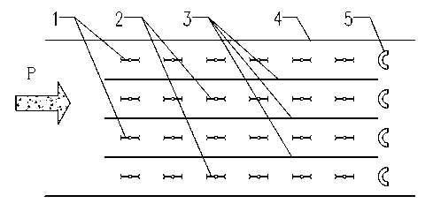
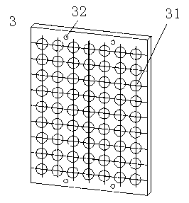
[0023] Such as figure 1 As shown, the fine particle removal device in this embodiment includes a housing 4, in which a number of grounding plates 3 arranged parallel to each other are arranged, wherein each grounding plate 3 is grounded, and the grounding plate 3 is densely covered with through holes . Two adjacent ground plates 3 form a channel as a channel through which the fine particles P pass. These channels are provided with discharge lines arranged along the length of the channel, wherein the discharge line set in one of the two adjacent channels is the first discharge line 1, and the other discharge line is set in the other of the two adjacent channels. The wire is the second discharge line 2, the first discharge line 1 is connected to the positive output power supply to discharge positive charges, and the second discharge line 2 is connected to the negative output power supply to discharge negative charges. The first discharge wire 1 and the second discharge wire 2 ma...


PUM

PropertyMeasurementUnit
Apertureaaaaaaaaaa

Abstract

The invention discloses a fine particle removal method which comprises the steps that fine particles enter a plurality of charged channels that are adjacent and parallel to one another along with air flow and are charged with positive charge and negative charge in every two adjacent charged channels respectively; and the fine particles charged in the charged channels pass through a plurality of particle channels for communicating every two adjacent charged channels and are collided, coagulated, and then trapped by a trapping device. In addition, the invention further provides a fine particle removal device which comprises a plurality of grounding electrode plates that are arranged in parallel to one another, a plurality of channels and the trapping device, wherein through holes are uniformly and densely distributed in the grounding electrode plates; a plurality of discharging wires are arranged in each of the channels in the length direction of each channel; the discharging wires in every two adjacent channels are connected with a positive output power supply and a negative output power supply respectively; and the trapping device is arranged at the back of the tail ends of the channels.

Description

Technical field [0001] The invention relates to a method for removing inhalable particulate matter and a corresponding device, in particular to a method for removing fine particulate matter and a corresponding device. Background technique [0002] PM 10 (Particulate matter with aerodynamic diameter da≤10μm) is called inhalable particulate matter, which can enter the lungs with breathing, while PM 2.5 (Particles with aerodynamic diameter da≤2.5μm) can also be deposited in human alveoli, leading to silicosis and other pulmonary diseases. With the increasingly stringent environmental standards, fine particulate matter will certainly become the focus of future environmental governance. [0003] The existing high-efficiency precipitators, such as electric precipitators and bag precipitators, are the most widely used. Due to the limitation of mechanism, the collection efficiency of fine particles of about 1 micron is low. Therefore, the capture of fine particles has become a hot researc...

Claims


Application Information

Patent Timeline
IPC IPC(8): B03C3/04B03C3/34B03C3/40
Inventor 刘道清何剑徐国胜石洪志周晶汪庆丰顾德仁朱亚平
Owner BAOSHAN IRON & STEEL CO LTD
Learn More