Roller guide and guard unit for loop

A guide device and guide roller technology, which is applied in the field of steel rolling equipment, can solve problems such as the inability to adjust the distance between guide rollers, and achieve the effects of improving operating efficiency, reducing use costs, and strong practicability

Inactive Publication Date: 2012-12-26
JIANGSU YONGGANG GROUP CO LTD
View PDF5 Cites 6 Cited by
  • Summary
  • Abstract
  • Description
  • Claims
  • Application Information

AI Technical Summary

Problems solved by technology

The rolled piece is arc-shaped in the looper, so the rolled piece is very easy to produce scratches on the guide plate of the guide, which may not have much impact on the general-purpose wire products, but for high-value-added wire products that require anti-slip scratches , It is required to test the performance of cold heading and hot heading. Wire products have particularly high requirements on the surface integrity of the rolled piece. For example, 1 / 3 of the 0.04mm scratch on the finished product will crack in the cold heading test. Calculated according to the area reduction rate, the entrance of the sizing rolling mill is reduced. A scratch of about 0.08mm on the rolled piece, and a scratch of about 0.2mm on the rolled piece at the entrance of the finishing mill will cause cracking in the cold heading test of the finished product. Therefore, for the rolling of high value-added products, the anti-scratch requirement is very important, especially for looper rolling. Due to the arc-shaped curve movement of the rolled piece, the guide device for guiding the rolled piece after the looper is generally a sliding guide, and there are also rolling guides with rolling elements, but the form is generally relatively simple, and the distance between the guide rollers cannot be adjusted.

Method used


Image

  • Roller guide and guard unit for loop
  • Roller guide and guard unit for loop

Examples


Embodiment Construction

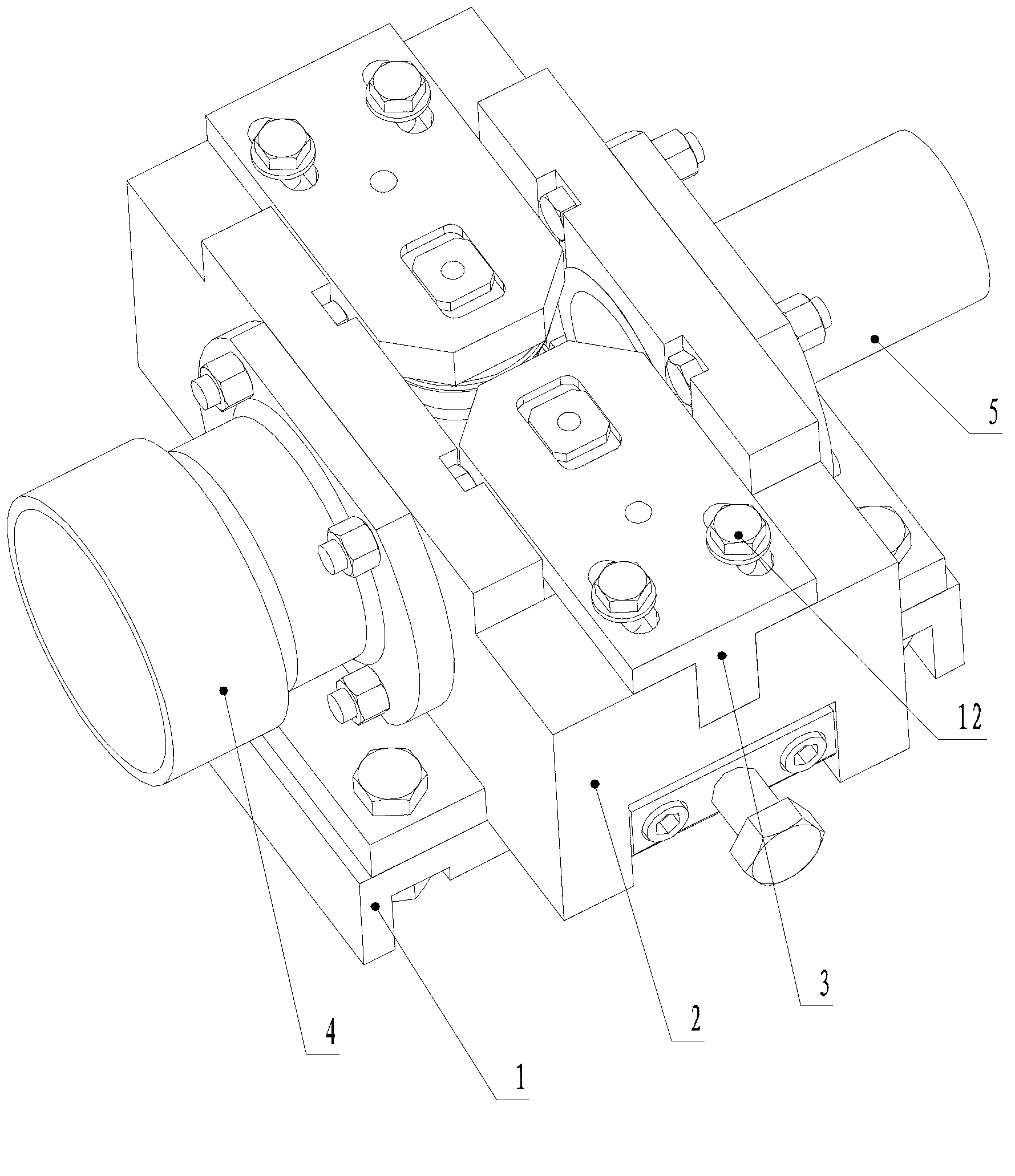
[0012] A rolling guide device for loopers provided in this embodiment has a structure as shown in the figure, including a bracket 1, a jacket 2 is fixed above the bracket by a hexagon head bolt 3, and an inlet conduit 4 is provided on the inlet side of the jacket. An outlet conduit 5 is provided on the outlet side. Wherein, guide roller seats 3 with the same structure are provided on the left and right sides above the jacket, and the two guide roller seats are of adjustable relative distance.

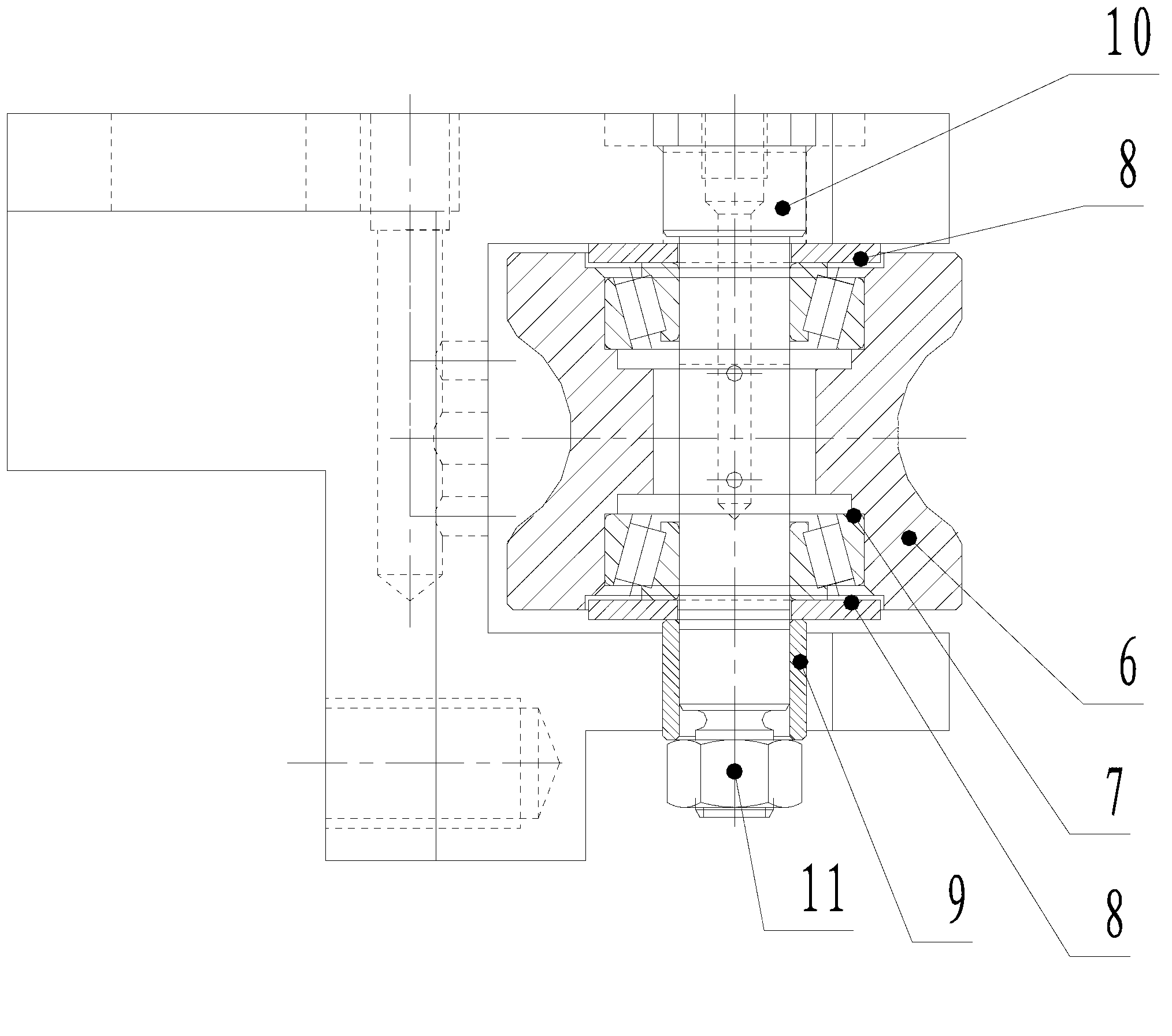
[0013] At the same time, a guide roller 6 is installed in the guide roller seat, and a guide roller shaft 10 runs through the guide roller, and two tapered roller bearings 7 are arranged symmetrically up and down outside the guide roller shaft, and an adjusting gasket 8 is installed outside the tapered roller bearing. , The outer end of the guide roller shaft is sleeved with a copper sleeve 9, and then tightened by a lock nut 11.

[0014] When in use, the guide roller seat is controlle...


PUM


Abstract

The invention relates to a roller guide and guard unit for a loop. The unit comprises a bracket; a guide pipe frame is installed above the bracket; an entrance guide pipe is arranged at an entrance of the guide pipe frame while an exit guide pipe is arranged at an exit of the guide pipe frame; two guide roller seats with the same structure are respectively arranged at the left and the right above the guide pipe frame; and the relative distance between the two guide roller seats can be adjusted. The roller guide and guard unit for the loop is suitable for rolling wire products with high added values, the surface of a rolled piece can be protected, no steel scratches and adhesion exist, and the surface of the rolled piece can be protected from being scratched. The abrasion of a guide slot is effectively reduced and the use cost of the guide slot is reduced. The roller guide and guard unit for the loop has the advantages of obvious design effect, strong practicability, improvement on working performance, simple structure, convenience for assembly and disassembly, simplicity and convenience in operation and low production cost.

Description

technical field [0001] The patent of the present invention relates to the technical field of steel rolling equipment, in particular to a guide device for loopers. Background technique [0002] At present, wire rod mills, reducing and sizing units, finishing units, and pre-finishing units are generally designed with looper devices at the front entrances. Some guides and guards guide and transition, and the general guides are sliding guides. The rolled piece is arc-shaped in the looper, so the rolled piece is very easy to produce scratches on the guide plate of the guide, which may not have much impact on the general-purpose wire products, but for high-value-added wire products that require anti-slip scratches , It is required to test the performance of cold heading and hot heading. Wire products have particularly high requirements on the surface integrity of the rolled piece. For example, 1 / 3 of the 0.04mm scratch on the finished product will crack in the cold heading test. ...

Claims


Application Information

Patent Timeline
Patent Type & Authority Applications(China)
IPC IPC(8): B21B39/16
Inventor 汪建元
Owner JIANGSU YONGGANG GROUP CO LTD
Why Eureka
Try Eureka