
Shifting device of electric hammer

A technology of electric hammers and shifting parts, which is applied in the direction of striking tools, light impact tools, manufacturing tools, etc., which can solve the problems of lack of manpower control and response speed, reduce operating efficiency of operators, and injuries of operators, so as to improve labor efficiency. Productivity and work quality, avoiding tooth punching phenomenon, and improving the effect of work quality

Inactive Publication Date: 2012-12-26
ZHEJIANG BENYU TOOLS
View PDF6 Cites 8 Cited by
  • Summary
  • Abstract
  • Description
  • Claims
  • Application Information

AI Technical Summary

Problems solved by technology

Due to the lack of manpower controllability and response speed, the phenomenon of tooth beating often occurs when the electric hammer shifts gears, resulting in premature damage to the electric hammer
In order to avoid the phenomenon of tooth beating, the operator needs to wait for the electric hammer to completely stop rotating before shifting gears. At this time, if the stop position of the transmission gear is staggered from the position of the gear shifting gear, the gear cannot be shifted, and the operator needs to turn the drill bit by hand. Adjust the position of the transmission gear, and only wait until the transmission gear matches the position of the gear shifting gear before shifting, which will reduce the working efficiency of the workers
If in case of misoperation, accidentally touch the power switch while turning the drill bit, the unexpected rotation of the drill bit will cause serious injury to the hands of the operator

Method used


Image

  • Shifting device of electric hammer
  • Shifting device of electric hammer
  • Shifting device of electric hammer

Examples


Embodiment

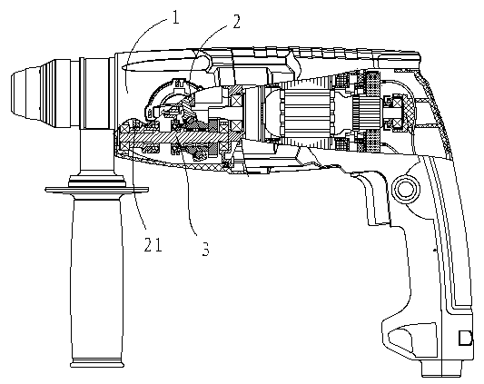
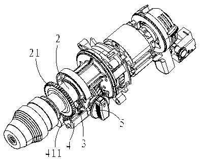
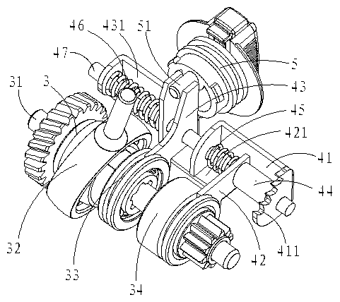
[0019] Embodiment: a gear shifting device of an electric hammer, such as figure 1 , figure 2 , image 3 As shown, the electric hammer 1 includes a transmission device 2, a shifting device 3, a shifting device 4, and a knob 5. The shifting device 3 includes an intermediate shaft 31, and an intermediate shaft gear that can be linked or disengaged from the intermediate shaft 31. 34. A clutch 33 that is linked with the intermediate shaft 31 in the circumferential direction and can move back and forth in the axial direction, and a swing rod bearing 32 that can be linked or disengaged by adjusting the position of the clutch 33 and the intermediate shaft 31. The transmission device 2 is provided with a large gear 21 , the large gear 21 meshes with the intermediate shaft gear 34 , the swing rod bearing 32 is connected with the transmission device 2 , and the driving rod 51 on the knob 5 is offset relative to the axial center of the knob 5 .

[0020] like image 3 , Figure 4 As s...


PUM


Abstract

The invention discloses a shifting device of an electric hammer, and the electric hammer comprises a drive device, a gear shift device, a shifting device and a knob, wherein the gear shift device comprises an intermediate shaft, an intermediate shaft gear, a clutch and an oscillating rod bearing, a large gear is arranged inside the drive device, the large gear is engaged with the intermediate shaft gear, the oscillating rod bearing is connected with the drive device, the shifting device comprises a first shifting member and a second shifting member, one end of the first shifting member and one end of the second shifting member are respectively connected with a shifting rod on the knob, the other end of the first shifting member is connected with the intermediate shaft gear, the other end of the second shifting member is connected with the clutch, and the first shifting member and the second shifting member are respectively connected with a resetting mechanism. The shifting device is simple in structure, reasonable in design, convenient to manufacture, capable of realizing the shifting of the electric hammer without stopping the electric hammer, not only capable of avoiding the tooth seizing phenomenon, but also capable of guaranteeing the personal safety of the operation personnel, and capable of improving the labor productivity and the working quality.

Description

technical field [0001] The invention relates to an electric tool, in particular to a shifting device of an electric hammer. Background technique [0002] Electric hammers generally have the functions of hammering, drilling, and hammering and drilling. The conversion between various functions is generally realized by changing the transmission mode between the shifting mechanism and the transmission mechanism through the shifting mechanism. At present, the electric hammer shifting mechanism in use is directly connected with the gear shifting mechanism by a lever connected with the knob, and the knob is rotated by hand to make the shifting lever produce a displacement to push the gear on the gear shifting mechanism to change the position to change the gear shifting mechanism. The meshing mode between the gear on the gear mechanism and the gear on the transmission mechanism, so as to realize the conversion between various functions of the electric hammer. Due to the lack of man...

Claims


Application Information

Patent Timeline
Patent Type & Authority Applications(China)
IPC IPC(8): B25D17/00
Inventor 尚才荣
Owner ZHEJIANG BENYU TOOLS
Learn More