Chain belt electroplating supporting frame and electroplating equipment using the same

A technology for chain belts and chain teeth, which is applied in applications, clothing, sliding fastener components, etc. It can solve problems such as no arbitrary bending, failure to ensure electrical contact, and damage to the electroplating reaction interface, and achieve high-quality electroplating.

Active Publication Date: 2012-12-26
铜陵嘉禾电子科技股份有限公司
View PDF5 Cites 14 Cited by
  • Summary
  • Abstract
  • Description
  • Claims
  • Application Information

AI Technical Summary

Problems solved by technology

[0003] In the above electroplating process, the zipper strip must be bent to contact the surface of the electroplating guide wheel, and the zipper strip does not have the ability to bend arbitrarily due to the existence of metal elements arranged at intervals
Therefore, during continuous electroplating, it is impossible to ensure that every chain tooth on the zipper is in effective electrical contact with these electroplated guide wheels, thereby affecting the quality of the electroplated zipper
Since these electroplating guide wheels directly contact with the side of the chain teeth of the zipper strip during electroplating, the electroplating reaction interface at this position is destroyed, and problems such as spots are easily generated on the electroplating layer

Method used


Image

  • Chain belt electroplating supporting frame and electroplating equipment using the same
  • Chain belt electroplating supporting frame and electroplating equipment using the same
  • Chain belt electroplating supporting frame and electroplating equipment using the same

Examples


Embodiment Construction

[0015] Below in conjunction with accompanying drawing and specific embodiment the present invention will be further described:

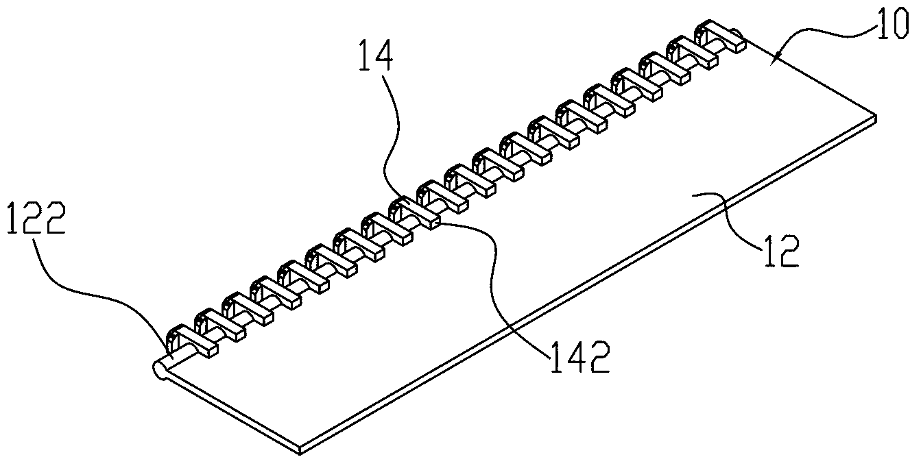
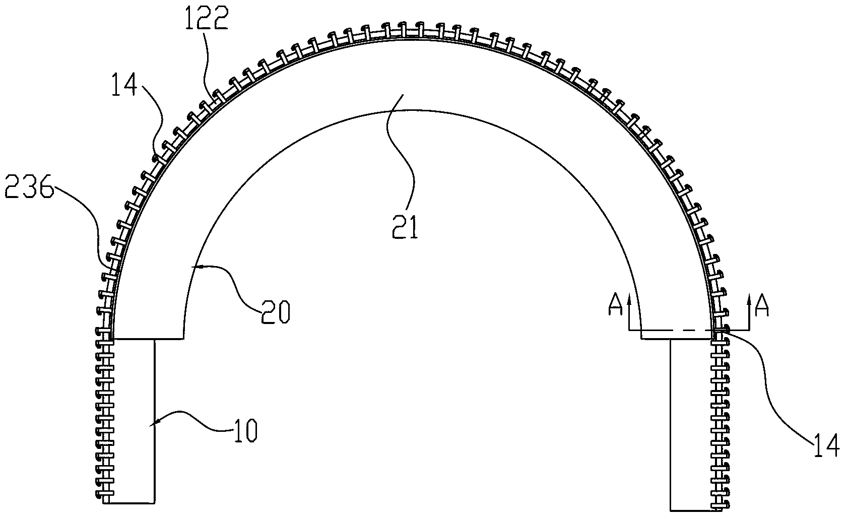
[0016] see figure 1 , figure 1 Shown is a perspective view of the zipper stringer 10 to be electroplated in the present invention. The chain belt 10 includes a fabric belt 12 and a plurality of metal fastener elements 14 disposed on the fabric belt 12 at intervals. Each metal fastener element 14 includes two legs 142 . The fabric belt 12 is provided with a fabric rib 122 on one side thereof, and the legs 142 of the metal fastener elements 14 are fixed on the fabric belt 12 by engaging the fabric rib 122 . The cloth tape 12 has a certain stretching elasticity along the stretching direction of the cloth tape 12 .

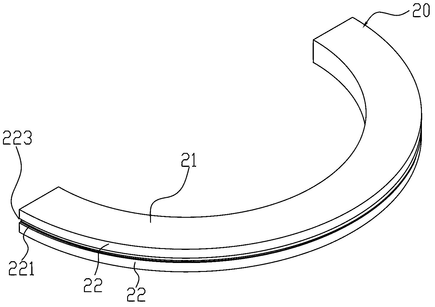
[0017] Please refer to figure 2 and Figure 5 , The chain belt electroplating bracket 20 of the first embodiment of the present invention includes a bracket body 21 and a chain belt traction mechanism, and the chain belt traction mech...


PUM


Abstract

Provided are a chain belt electroplating supporting frame and electroplating equipment using the chain belt electroplating supporting frame. The chain belt electroplating supporting frame is used to electrify metal chain teeth on a chain belt in the process of electroplating, and comprises a supporting frame body and a chain belt traction mechanism, wherein the supporting frame body is provided with an outer side surface, the outer side surface is in an outward protruding arc-shaped structure and is provided with a containing groove, the width of the containing groove is the width between two leg portions of the chain teeth, the containing groove is used to contain a cloth belt of the chain belt, the outer side surface close to the containing groove is provided with a conductive belt which is fixed on the outer side surface, a part of the surface of the conductive belt is in electric connection with the bottoms of chain teeth, the part of the surface of the conductive belt not contacting the chain teeth is covered by an anti-corrosion layer, and the chain belt traction mechanism is used to drag the chain belt along the stretching direction of the chain belt when the chain belt is wound on the supporting frame body and exert tension force to the chain belt. The chain belt electroplating supporting frame and the electroplating equipment using the chain belt electroplating supporting frame have the advantages of being high in electroplating quality.

Description

technical field [0001] The invention relates to an electroplating bracket and electroplating equipment using the bracket, in particular to a chain belt electroplating bracket used for electroplating the chain belt of a zipper and the electroplating equipment using the bracket. Background technique [0002] At present, in order to enhance the aesthetics of the zipper elements and improve the wear resistance and corrosion resistance, the industry usually uses metal deposition to coat the surface of the zipper elements on the zipper belt. Since the chain teeth of the metal zipper need to be implanted on the chain belt one by one, the metal chain teeth will be deformed during the implantation process, so the metal deposition of the chain teeth needs to be carried out after the chain belt is implanted. Commonly used metal deposition methods are electroless plating and electroplating. When electroless plating is used for plating, a zipper with good wear resistance cannot be obtai...

Claims


Application Information

Patent Timeline
Patent Type & Authority Applications(China)
IPC IPC(8): C25D7/02
Inventor 李甫文
Owner 铜陵嘉禾电子科技股份有限公司
Why Eureka
Try Eureka