
Intelligent power distribution switch control circuit fault detection circuit and detection method thereof

A technology for switching control loops and fault detection circuits, applied in electrical testing/monitoring, measuring current/voltage, measuring electricity, etc., can solve the problems of marking, inability to distinguish between types of refusal, and indistinguishable fault types, achieving a simple circuit structure , the detection results are reliable, the effect of improving reliability and intelligence

Active Publication Date: 2012-12-26
BEIJING HEROSAIL POWER SCI & TECH
View PDF5 Cites 19 Cited by
  • Summary
  • Abstract
  • Description
  • Claims
  • Application Information

AI Technical Summary

Problems solved by technology

[0005] The purpose of the present invention is to provide an intelligent power distribution switch control loop fault detection circuit to solve the technical problem that the type of refusal to operate cannot be distinguished when the power distribution switch fails
[0006] Another object of the present invention is to provide a method for detecting circuit faults using the above detection circuit to solve the technical problem that fault types cannot be distinguished and marked

Method used


Image

  • Intelligent power distribution switch control circuit fault detection circuit and detection method thereof
  • Intelligent power distribution switch control circuit fault detection circuit and detection method thereof
  • Intelligent power distribution switch control circuit fault detection circuit and detection method thereof

Examples


Embodiment Construction

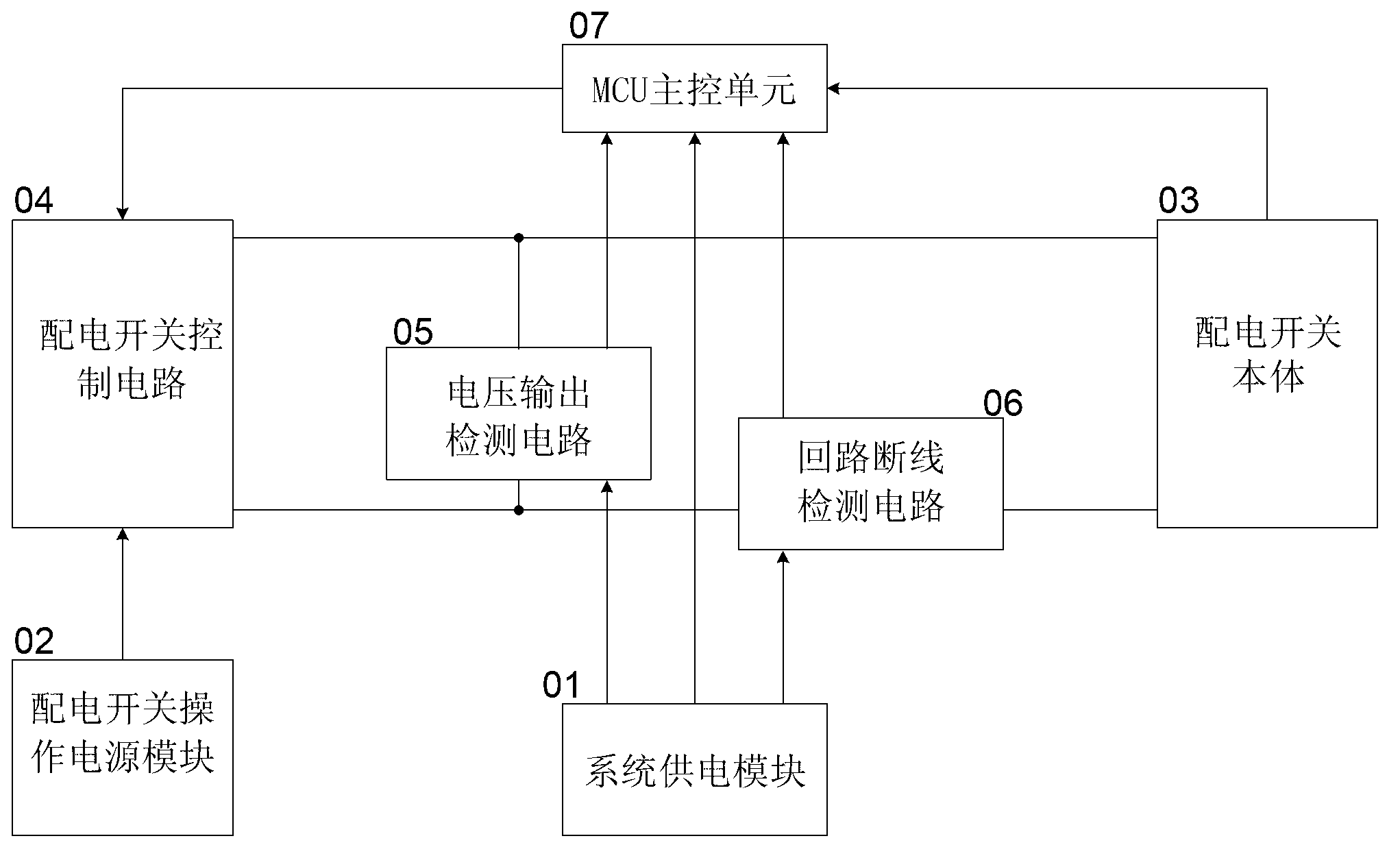
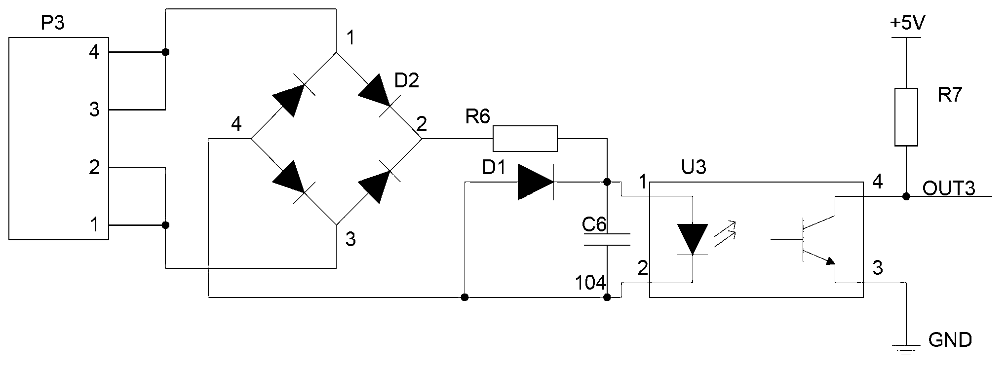
[0028] like figure 1 As shown, the intelligent power distribution switch control loop fault detection circuit in this embodiment includes a voltage output detection circuit 05, a loop disconnection detection circuit 06, and an MCU main control unit 07, wherein:

[0029] The voltage output detection circuit 05 is used to connect the voltage output terminal of the power distribution switch control circuit 04, collect the real-time voltage change signal output by the power distribution switch control circuit 04, and transmit it to the MCU main control unit 07;

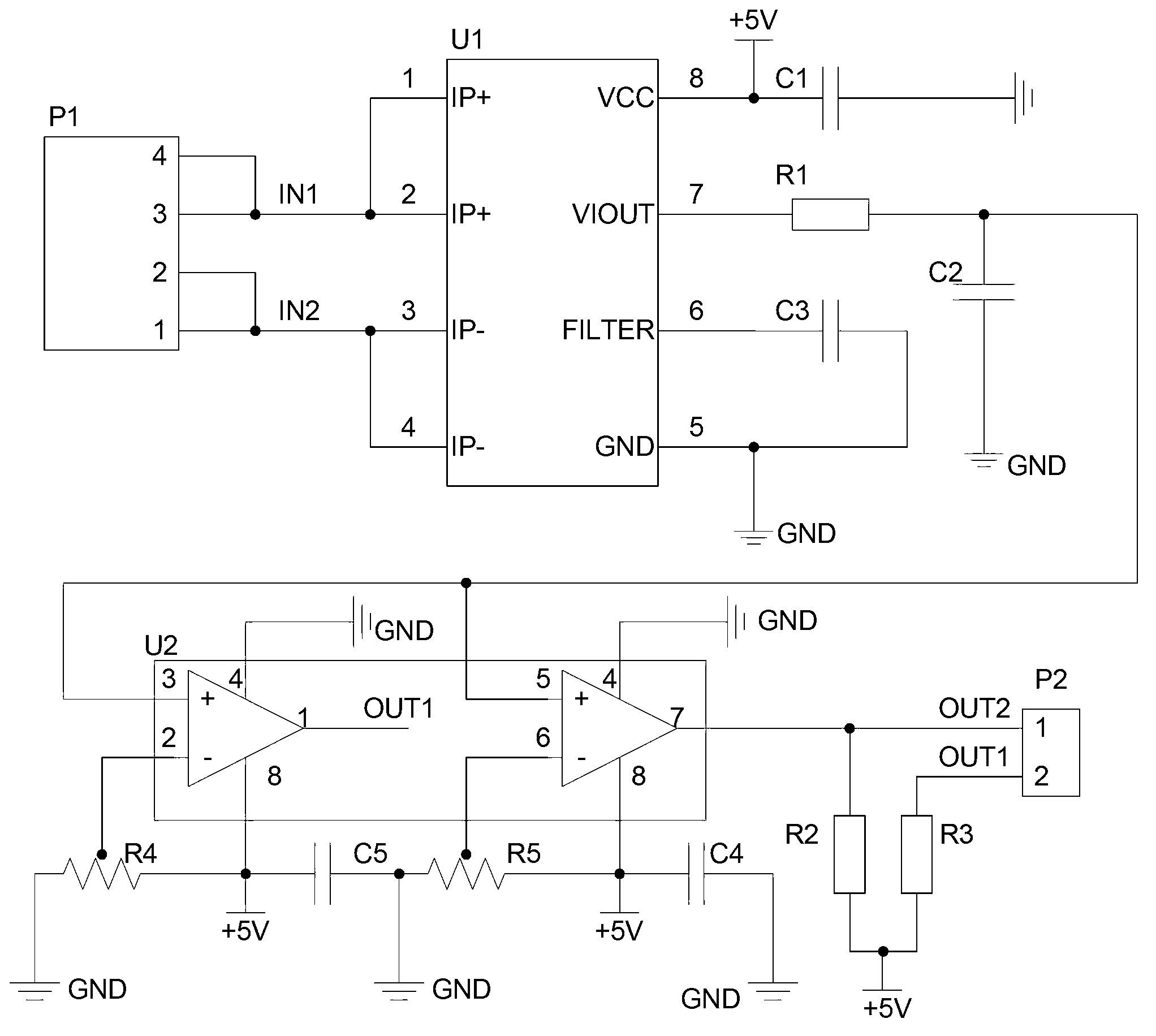
[0030] The loop disconnection detection circuit 06 is used to collect the real-time current change signal of the control loop formed by the power distribution switch control circuit 04 and the power distribution switch body 03, and transmit it to the MCU main control unit 07;

[0031] The MCU main control unit 07 is used to receive the signals transmitted by the voltage output detection circuit 05 and the loop disconnecti...


PUM


Abstract

An intelligent power distribution switch control circuit fault detection circuit comprises a power distribution switch operational power supply module and further comprises a voltage output detection circuit, a return circuit line break detection circuit and a main control unit (MCU), wherein the voltage output detection circuit is used for being connected with a voltage output end of a power distribution switch control circuit, collecting real-time voltage change signals output by the power distribution switch control circuit, and transmitting the real-time voltage change signals to the MCU; the return circuit line break detection circuit is used for collecting real-time current change signals of a control return circuit formed by the power distribution switch control circuit and a power distribution switch body, and transmitting the real-time current change signals to the MCU; the MCU is used for receiving signals transmitted by the voltage output detection circuit and the return circuit line break detection circuit and receiving signals of each contact of the power distribution switch body, judging working conditions of the control return circuit, sending control signals to the power distribution switch control circuit according to the working conditions of the control return circuit, and sending working condition signals to a primary station in a long distance, so that judge of fault category is achieved. The invention further comprises a detection method.

Description

technical field [0001] The invention relates to a detection circuit and a detection method, in particular to a detection circuit and a detection method for detecting the circuit current and output voltage of a power distribution switch. Background technique [0002] Usually, high-voltage circuit breakers and high-voltage isolation power distribution switches include power distribution switch bodies, power distribution switch control circuits, and power distribution switch operating power supplies for power distribution switch control circuits. Power distribution switch bodies include power distribution switch main contacts and power distribution switches. Electrical switch auxiliary contacts. Auxiliary contacts of power distribution switches, as small-capacity contacts that act synchronously with the main contact (or main switch) in time, are usually used in corresponding secondary circuits to provide power distribution switches for protection, control, signal, and measureme...

Claims


Application Information

Patent Timeline
Patent Type & Authority Applications(China)
IPC IPC(8): G05B23/02G01R19/00G01R31/02
CPCY04S10/52
Inventor 刘玉刚张焕臣黄小林
Owner BEIJING HEROSAIL POWER SCI & TECH
Learn More