Magnetic ink removing machine

An ink and magnetic technology, applied in the field of magnetic ink remover, can solve the problems of poor processing effect and large energy consumption, and achieve the effect of improving effect, good processing effect and low operating cost

Inactive Publication Date: 2013-01-02
HUBEI BAOTA PAPER
View PDF0 Cites 1 Cited by
  • Summary
  • Abstract
  • Description
  • Claims
  • Application Information

AI Technical Summary

Problems solved by technology

To deal with this kind of mixed office waste paper, most of them use the method of heat disperser. The problem is that the energy consumption is large and the treatment effect is poor. At present, there is no other cheaper method.

Method used


Image

  • Magnetic ink removing machine

Examples


Embodiment Construction

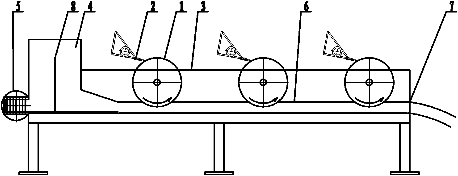
[0016] Such as figure 1 Among them, a magnetic ink removal machine, the frame 3 is provided with at least one magnetic roller 1, the magnetic roller 1 is connected with the rotary drive device, one side of the magnetic roller 1 is provided with a scraper 2 in contact with the magnetic roller 1, and the frame 3 One end is provided with a headbox 4, and the other end is provided with a pulp outlet 7. There are two or three magnetic rollers 1 used in this example. The magnetic force roller 1 is installed in the tank body of the frame 3, and the lower end of the magnetic force roller 1 is immersed in the below of the slurry liquid level 6.

[0017] The elevation of the upper end of the headbox 4 is higher than that of the frame 3 . A partition 8 is arranged inside the headbox 4 . The elevation of the upper end of the partition 8 is between the elevation of the upper end of the headbox 4 and the elevation of the upper end of the frame 3 . One side of the lower end of the headbo...


PUM


Abstract

A magnetic ink removing machine is provided on a chassis with at least one magnetic roller, which is connected with a rotation drive device and provided at one side with a scraper contacting the magnetic roller, and the chassis is provided at one end with a head box and at the other end with a paste outlet. The ink removing machine utilizes the principle that ink raw material of office waste paper is ferric oxide capable of realizing magnet adsorption, to perform adsorption via magnetic roller made of magnet, to thereby remove ink in the paste. Compared with thermal dispersion machine, the ink removing machine has lower cost, less investment, lower operation cost and better treatment effect.

Description

technical field [0001] The invention relates to the field of waste paper pulp treatment, in particular to a magnetic ink removal machine for removing ink in waste paper pulp. Background technique [0002] In the waste paper deinking process, due to the mixed waste paper, there are various types of waste paper, especially some office waste paper mixed in it, which brings certain difficulties to the ink removal. The difficulty is that the ink of office waste paper cannot be removed or even harmful by conventional chemical methods, while other types of inks rely on chemical methods to be very effective. Due to the unclean removal of ink, many black dust spots are brought to the paper surface, thereby reducing the product quality and making the treatment of this kind of waste paper a worldwide problem. To deal with this kind of mixed office waste paper, most of them use the method of heat disperser. The problem is that the energy consumption is large and the treatment effect is...

Claims


Application Information

Patent Timeline
Patent Type & Authority Applications(China)
IPC IPC(8): D21C5/02
CPCY02W30/64
Inventor 王晓华
Owner HUBEI BAOTA PAPER
Why Eureka
Try Eureka