Sludge discharge equipment comprising vacuum pump and sludge discharge tank

A technology of vacuum pump and sludge discharge tank, applied in mining equipment, drainage, safety devices, etc., can solve the problem of easy damage of water pump, and achieve the effect of long service life, long conveying distance, convenient operation and maintenance

Inactive Publication Date: 2013-01-02
CENT SOUTH UNIV
View PDF4 Cites 5 Cited by
  • Summary
  • Abstract
  • Description
  • Claims
  • Application Information

AI Technical Summary

Problems solved by technology

Its disadvantages are: the water pump often transports water with high sediment content, and the water pump is easy to damage

Method used


Image

  • Sludge discharge equipment comprising vacuum pump and sludge discharge tank
  • Sludge discharge equipment comprising vacuum pump and sludge discharge tank

Examples


Embodiment Construction

[0015] specific implementation plan

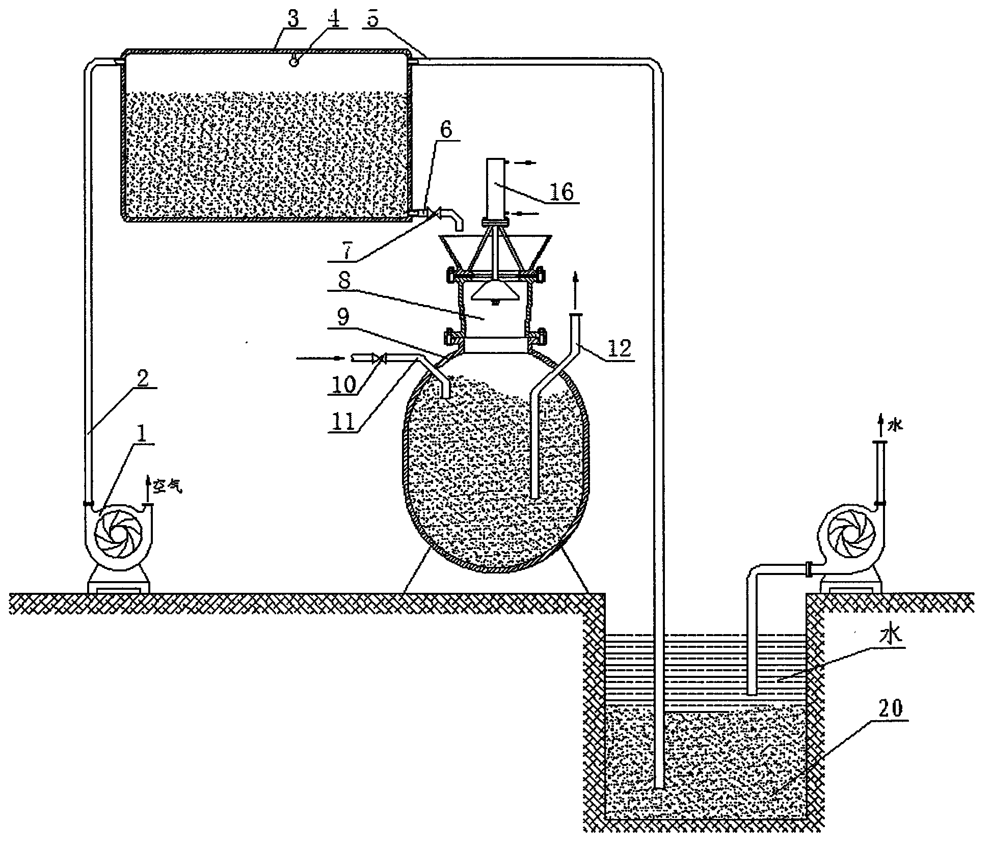
[0016] figure 1 Middle, 1. Vacuum pump, 2. Suction pipe, 3. Mud storage tank, 4. Liquid level gauge, 5. Suction mud pipe, 6. Mud discharge pipe, 7. Mud discharge valve, 8. Bell valve, 9. Discharge Clay pot, 10, air intake valve, 11, air intake pipe, 12, delivery pipe.

[0017] exist figure 1 Among them, the mud storage tank (3) is placed under the mud discharge tank (9), and a suction pipe (2) is arranged above the left end to connect with the vacuum pump (1), and a liquid level gauge (4) is installed above the tank, A mud suction pipe (5) is provided above the right end and goes deep into the silt of the water tank, and a mud discharge pipe (6) and a mud discharge valve (7) are provided below the right end, and the mud is discharged from the water tank under the action of the vacuum pump (1). It is sucked into the mud storage tank (3), and put into the mud discharge tank (9) through the mud discharge valve (7). The mud discharge tank ...


PUM


Abstract

Sludge discharge equipment comprising a vacuum pump and a sludge discharge tank consists of the vacuum pump, an air suction pipe, a sludge storage tank, a liquid level meter, a sludge suction pipe, sludge discharge pipe, a sludge discharge valve, a bell-type valve, the sludge discharge tank, an air inlet valve, an air inlet pipe and a delivery pipe. The sludge storage tank is arranged above the sludge discharge tank, the air suction pipe is arranged on the left end of the sludge storage tank and is connected with the vacuum pump, the liquid level meter is installed at the inner upper part of the sludge storage tank, the sludge suction pipe is arranged on the right end of the sludge storage tank and extends into sludge in a water sump, the sludge discharge pipe is arranged below the right end of the sludge storage tank and is provided with the sludge discharge valve, and the sludge in the water sump is sucked into the sludge storage tank from the water sump under the action of the vacuum pump. The sludge discharge tank is arranged below the sludge storage tank, a feed port is formed in the upper end of the sludge discharge tank and is connected with the bell-type valve for controlling slurry to flow into, the air inlet pipe and the air inlet valve are arranged on the left upper end of the sludge discharge tank for controlling high pressure air to flow into the sludge discharge valve, and the delivery pipe is installed on the right upper end of the sludge discharge tank for delivering the slurry. The sludge discharge equipment has the advantages of simple equipment, convenience in maintenance, large delivery capacity, long service life, long delivery distance and less investment.

Description

technical field [0001] The present invention relates to a kind of equipment for cleaning the silt in the underground water tank of the mine, in particular to a kind of equipment which first adopts the vacuum pump to suck the sludge in the underground water tank of the mine into the mud storage tank, and then puts the mud in the mud storage tank into the sludge discharge tank. In the tank, the mud in the mud tank is conveyed to the designated place by pneumatic force. technical background [0002] At present, due to the ubiquity of groundwater in mining operations, some mines also use hydraulic methods for filling. In order to discharge groundwater and filling water from the surface and ensure the normal operation of the mine, a drainage system is generally established underground for ore. The drainage system includes water tanks. , water pumps and drainage pipes. [0003] During the mining process, powder ore is produced due to the effects of blasting and collision. When hy...

Claims


Application Information

Patent Timeline
Patent Type & Authority Applications(China)
IPC IPC(8): E21F16/00
Inventor 徐海良谢秋敏李峰刘大帅
Owner CENT SOUTH UNIV
Why Eureka
Try Eureka