
Intelligent-control non-retractable synchronous soot blower system

A soot blower, non-telescopic technology, applied in the treatment of combustion products, combustion methods, removal of solid residues, etc., can solve the problems of easy leakage of the sleeve, low soot blowing efficiency, waste of steam, etc., and reduce equipment. High usage, high soot blowing efficiency, and the effect of reducing land occupation

Inactive Publication Date: 2013-01-02
YANGZHOU GOLDSTAR TECH IND
View PDF6 Cites 3 Cited by
  • Summary
  • Abstract
  • Description
  • Claims
  • Application Information

AI Technical Summary

Problems solved by technology

Its structure is complex, and air leakage is prone to occur between the sleeves, and the reliability is low
The soot blowing pipe rotating in a full circle is spraying steam, while the convection pipe in the convection chamber is only on the upper and lower sides of the soot blowing pipe. The whole circle of air injection makes the steam spraying to the furnace wall invalid when the soot blowing pipe is turned to the horizontal position. Injection, wasting steam; steam is blown out through the hole, soot blowing efficiency is low

Method used


Image

  • Intelligent-control non-retractable synchronous soot blower system
  • Intelligent-control non-retractable synchronous soot blower system

Examples


Embodiment 1

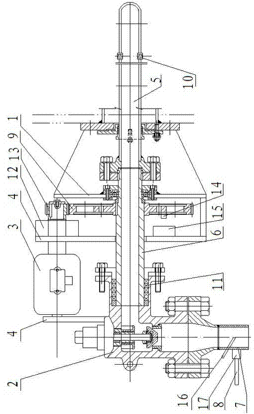
[0015] like figure 1 As shown, the present invention mainly consists of an industrial furnace connection mechanism 1, a soot blowing solenoid valve 2, a motor 3, a motor support plate 4, a soot blowing pipe 5, a soot blowing pipe connecting pipe 6, a steam connecting pipe 7, a heating pipe waste gas pipe 8 and a deceleration Device 12 is composed.

[0016] The soot blowing connecting pipe 6 is connected in the industrial furnace connecting mechanism 1, the soot blowing connecting pipe 6 is also fixedly connected with the transmission gear 9, the front end of the soot blowing connecting pipe 6 is connected with the soot blowing pipe 5, and the soot blowing pipe 5 is also opened There is a steam nozzle 10, the rear end of the soot blowing connecting pipe 6 communicates with the outlet of the soot blowing solenoid valve 2, and a sealing packing 11 is embedded in the connection between the soot blowing connecting pipe 6 and the outlet of the soot blowing solenoid valve 2.

[0...

Embodiment 2

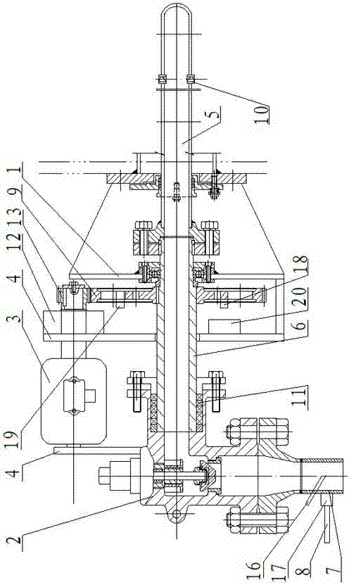
[0020] like figure 2 As shown, the structure of embodiment 2 is the same as that of embodiment 1, and the receiving device 15 of the angle measuring ruler sensing element 14 and the angle measuring ruler sensing element adopts a proximity switch, and two different angles of the transmission gear 9 are respectively equipped with a sending mechanism of the proximity switch. Terminals 18 and 19, a receiving terminal 20 of a proximity switch is installed on the industrial furnace connection mechanism 1.

[0021] Working process of the present invention:

[0022] When the system starts to blow soot, open the solenoid valve 17 of the warming pipe, the steam enters the pipeline system before the soot blower, and enters the waste steam pipe 8 of the warming pipe, and the waste steam pipe 8 of the warming pipe is connected to the waste gas recovery system of the factory system to realize recycling and achieve the goal of design. After a certain period of time, the thermocouple 16 det...


PUM


Abstract

The invention discloses an intelligent-control non-retractable synchronous soot blower system and belongs to the technical field of energy conservation of industrial heating furnaces and boilers. The system comprises an industrial furnace connection mechanism, a soot blowing solenoid valve, an electric motor, an electric motor supporting plate, a soot blowing pipe, a soot blowing pipe connection pipe, a steam connection pipe, a heating pipe waste gas pipe and a speed reducer, wherein the soot blowing pipe connection pipe is connected inside the industrial furnace connection mechanism in a penetrating mode, the front end of the soot blowing pipe connection pipe is connected with the soot blowing pipe, the rear end of the soot blowing pipe connection pipe is communicated with an outlet of the soot blowing solenoid valve, and the electric motor supporting plate is installed on one side of the industrial furnace connection mechanism. According to the system, an independent heating pipe system is canceled, the device usage amount can be reduced, the land occupation can be reduced, the control amount can be reduced, safety hazards can be reduced, an original electric control cabinet system is omitted, the manufacturing cost of the system is reduced, the steam consumption amount is reduced, the reliability is high, the soot blowing efficiency is high, the intelligent automatic soft control is achieved, the manufacturing is simple, and the power consumption is low.

Description

technical field [0001] The invention belongs to the technical field of energy saving of industrial heating furnaces and boilers, and specifically relates to an intelligently controlled non-telescopic synchronous soot blower system, which is mainly used for steam soot blowing of industrial heating furnace convection chambers, convection tubes and industrial boiler furnace tubes. Background technique [0002] At present, the steam soot blowers used in the convection chamber and convection tube of the industrial heating furnace and the furnace tube of the industrial boiler adopt relatively advanced superheated steam soot blowers. This type of soot blower is driven by the mechanical structure of the variable speed rotating gear, the conduction of the steam is controlled by the quasi-disk and the travel switch, and the high temperature and high pressure superheated steam is ejected through the casing structure to realize the soot blowing of the convection tube bundle, etc. . Its...

Claims


Application Information

Patent Timeline
IPC IPC(8): F23J1/00F23J3/02
Inventor 葛京鹏刘春生靳世平关欣黄素逸张洪伟刘志杰
Owner YANGZHOU GOLDSTAR TECH IND
Features
  • Generate Ideas
  • Intellectual Property
  • Life Sciences
  • Materials
  • Tech Scout
  • Unparalleled Data Quality
  • Higher Quality Content
  • 60% Fewer Hallucinations
Learn More