

Liquid crystal backlight driving current control device
A backlight drive and current control technology, applied in instruments, static indicators, etc., can solve the problems of single implementation scheme and strong dependence, and achieve the effect of realizing switching, reducing requirements, and reducing the requirements of dynamic adjustment speed.
- Summary
- Abstract
- Description
- Claims
- Application Information
AI Technical Summary
Problems solved by technology
Method used
Image

Examples
Embodiment 1
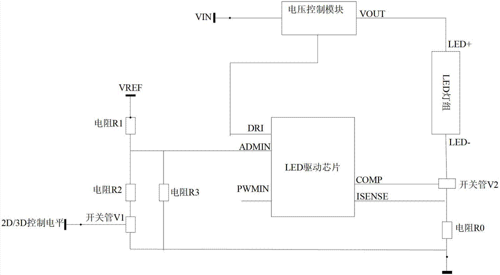
[0082] The embodiment of the present application provides a device for controlling the driving current of the liquid crystal backlight, such as Figure 4 As shown, the P-MOS tube and the N-MOS tube are used as the first electronic switch and the second electronic switch, and a main circuit module composition diagram of the device is given. Specifically, the liquid crystal backlight in the embodiment of the application Devices for drive current control, including:
[0083] Control unit; including the first control unit CHIP0 and the second control unit CHIP1; CHIP1 receives the display mode switching signal 2D / 3D_In from CHIP0; CHIP1 contains at least two electronic switches: P-MOS tube M1 and N-MOS tube M2, Among them, the source of M1 is connected to the power supply voltage pin VCC of CHIP2, the gate is connected to the control signal N_Control1 inside CHIP1, the drain is connected to the source of M2, the gate of M2 is connected to another control signal N_Control2 inside C...
Embodiment 2
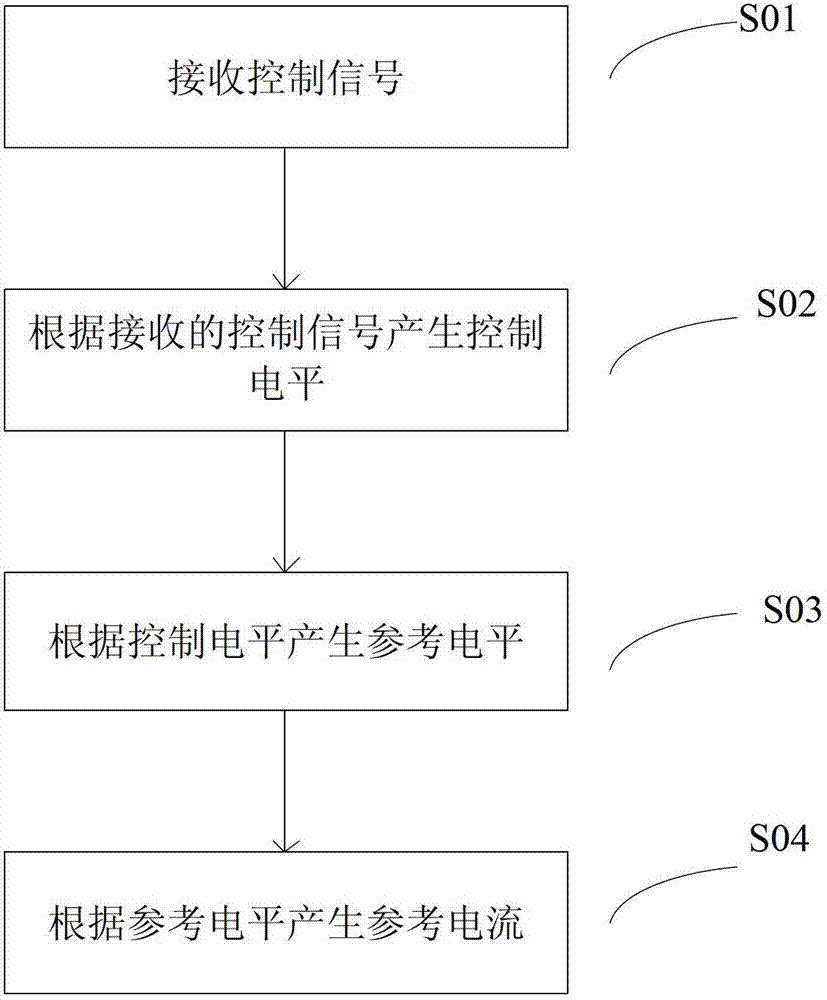
[0101] The embodiment of the present application provides a method for controlling the driving current of the liquid crystal backlight, which is applied to the device for driving the current of the liquid crystal backlight in the above embodiment, see image 3 , the specific steps include:
[0102] S01, receiving a control signal.
[0103] Specifically, it is: the control unit receives a control signal from the main control unit of the whole machine. In the embodiment of the present application, the control signal can be: a signal requesting to switch the display mode, specifically: instructing to switch from 2D display to 3D display Or switch from 3D display to 2D display signal. combine Figure 4 , the first control unit CHIP0 sends a signal 2D / 3D_In to switch the display mode, which is the received control signal.
[0104] S02. Generate a control level based on the control signal.
[0105] Specifically, it is: according to the received control signal for switching the d...
PUM
 Abstract
Description
Claims
Application Information