Electrically conductive structure

A conductive structure, conductive wire technology, applied in circuits, electrical components, braided wire conductors, etc., can solve problems such as instability, expensive nanotechnology, and three-dimensional lightning protection methods that do not provide composite materials or structures

Active Publication Date: 2013-01-02
THE BOEING CO
View PDF6 Cites 9 Cited by
  • Summary
  • Abstract
  • Description
  • Claims
  • Application Information

AI Technical Summary

Problems solved by technology

However, nanotechnology is expensive and unstable
Also, nanotechnology currently does not off

Method used


Image

  • Electrically conductive structure
  • Electrically conductive structure
  • Electrically conductive structure

Examples


Embodiment Construction

[0016] The following detailed description is merely exemplary in nature and is not intended to limit the described embodiments or the application and uses of the described embodiments. As used herein, the word "exemplary" or "illustrative" means "serving as an example, instance, or illustration." Any implementation described herein as "exemplary" or "illustrative" is not necessarily to be construed as preferred or advantageous over other implementations. All implementations described below are exemplary implementations provided to enable those skilled in the art to practice the present disclosure and are not intended to limit the scope of the claims. Furthermore, there is no intention to be bound by any expressed or implied theory presented in the preceding technical field, background, brief summary or the following detailed description of the invention.

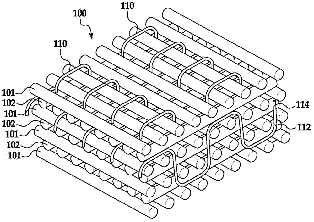
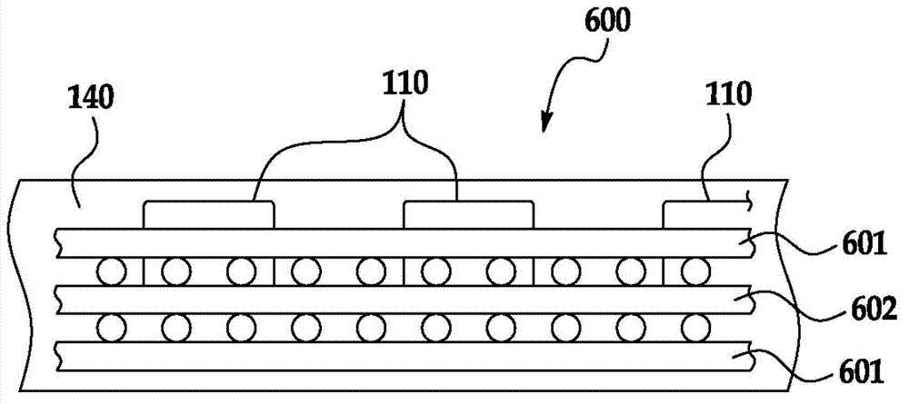
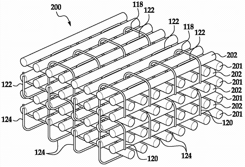
[0017] The present disclosure generally relates to conductive structures and methods of dissipating electrical current in...


PUM


Abstract

An electrically conductive structure includes a plurality of carbon fiber layers and at least one electrically conductive filament three-dimensionally woven among the carbon fiber layers. The plurality of carbon fiber layers and the at least one electrically conductive filament are operable to conduct electrical current throughout the structure.

Description

technical field [0001] In general, the present disclosure relates to structures that dissipate electrical current. More specifically, the present disclosure relates to conductive composite structures throughout which an electrically dissipative material is three-dimensionally woven to dissipate electrical current along the X, Y, and Z axes of the structure. Background technique [0002] In a variety of applications, composite structures are designed to withstand the currents and voltages of lightning strikes. This capability can be achieved by spraying or applying a metal mesh or screen to the exterior surface of the composite structure over the conductive coating. While these methods and techniques may be suitable for dissipating current along the X and Y axes (along the surface) of a composite structure, they may be ineffective in dissipating current in the Z direction (through the thickness) of the structure. Thus, electrical current from a lightning strike or short cir...

Claims


Application Information

Patent Timeline
IPC IPC(8): H01B5/12H01B13/00
CPCB64D45/02B32B5/22B32B5/024B32B2262/106B32B2307/202B32B15/02Y10T442/3195Y10T442/3065D03D1/0088D03D13/004D03D15/258H10K85/221
Inventor K·M·雷斯A·K·普里查德
Owner THE BOEING CO
Why Eureka
Try Eureka