
Feed overload protection device and device used for current monitoring
A technology of overload protection and feeding device, which is applied to emergency protection circuit devices, emergency protection circuit devices, circuit devices and other directions for limiting overcurrent/overvoltage, and can solve problems such as not being able to achieve comprehensive protection.
- Summary
- Abstract
- Description
- Claims
- Application Information
AI Technical Summary
Problems solved by technology
Method used
Image

Examples
Embodiment Construction
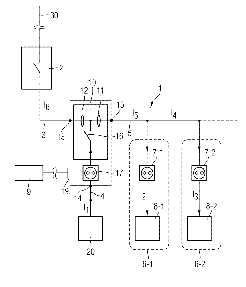
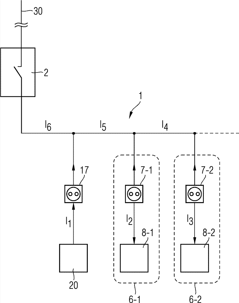
[0024] In FIG. 1 , according to the prior art, a device is schematically shown for monitoring when feeding in electrical power to an existing electrical network 1 already present in a building. current. The consumer network 1 has an overcurrent protection device 2 for protecting the consumer network 1 against electrical overload. Via the overcurrent protection device 2 , the consumer network 1 is electrically conductively connected to an energy distribution network 30 . Furthermore, the consumer network 1 has a first consumer branch 6 - 1 and a second consumer branch 6 - 2 electrically connected in parallel thereto. The first electrical consumer branch 6 - 1 and the second electrical consumer branch 6 - 2 each have an electrical plug connection in the form of a socket 7 - 1 or 7 - 2 . The electric load 8-1 or 8-2 is connected with the socket 7-1 or 7-2 respectively. In the running state, the current I 2 Flows to the electrical load 8-1 of the first power-consuming branch 6...
PUM
 Abstract
Description
Claims
Application Information