Control circuit for working state of vehicle-mounted wireless charger and control method thereof

A working state, vehicle wireless technology, applied in battery circuit devices, current collectors, circuit devices, etc., can solve the problems of complex radio frequency circuits and high cost, and achieve the effect of simple circuit structure, low cost and high reliability

Inactive Publication Date: 2013-01-02
CHERY AUTOMOBILE CO LTD
View PDF3 Cites 5 Cited by
  • Summary
  • Abstract
  • Description
  • Claims
  • Application Information

AI Technical Summary

Problems solved by technology

However, the radio frequency circuit is relatively complex and the cost is high

Method used


Image

  • Control circuit for working state of vehicle-mounted wireless charger and control method thereof

Examples


Embodiment 1

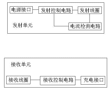
[0020] Such as figure 1 As shown, the vehicle wireless charger working state control circuit of this embodiment includes a transmitting unit and a receiving unit, wherein the transmitting unit includes a power interface, a transmitting control circuit and a transmitting coil, and the receiving unit includes a receiving coil, a receiving control circuit and a charging interface; the key The transmitting unit further includes a current detecting circuit for detecting the current of the transmitting coil, and the output end of the current detecting circuit is connected with the transmitting control circuit.

[0021] The transmission control circuit has two output signal frequencies, the two output signal frequencies are the resonant frequency F1 and the idle state frequency F0 not equal to the resonant frequency; and the transmitting coil has three output currents I1, I2, I3, wherein I1

[0022] The control method of the above-mentioned on-board wireless charger working ...


PUM


Abstract

The invention provides a control circuit for a working state of a vehicle-mounted wireless charger and a control method thereof. The control circuit for the working state of the vehicle-mounted wireless charger has the advantages of simple principle and low cost and comprises a transmitting unit and a receiving unit, wherein the transmitting unit comprises a power supply interface, a transmission control circuit and a transmission coil, and the receiving unit comprises a reception coil, a reception control circuit and a charging interface. A key point is that the transmitting unit also comprises a current detection circuit used for detecting the current of the transmission coil, and the output end of the current detection circuit is connected with the transmission control circuit. Real-time detection of the output current of the transmission coil is performed by the transmitting unit through the current detection circuit, and whether the receiving unit is located in a receiving area or not is judged according to the output current of the transmission coil, so as to change the frequency of output signals according to the position of the receiving unit. The control circuit for the working state of the vehicle-mounted wireless charger has the advantages of simple circuit structure, high reliability, low cost and the like, and the control method is accurate and reliable.

Description

technical field [0001] The invention relates to the technical field of vehicle-mounted mobile phone charging, in particular to a circuit for controlling the working state of a vehicle-mounted wireless charger and a control method thereof. Background technique [0002] The on-board wireless charger is divided into two parts: the transmitting unit and the receiving unit. The transmitting unit is connected to the vehicle power supply and emits energy through wireless radiation. The receiving unit receives the energy and charges the charging device (such as a mobile phone). The receiving unit receives energy within a defined area, while the transmitting unit needs to determine whether the receiving unit is within the defined receiving area. The current multi-purpose radio frequency module scheme, that is, the transmitting unit and the receiving unit are equipped with a radio frequency circuit and antenna that cooperate with each other. When the receiving unit enters the working...

Claims


Application Information

Patent Timeline
Patent Type & Authority Applications(China)
IPC IPC(8): H02J7/02
Inventor 王晓辉张芬
Owner CHERY AUTOMOBILE CO LTD
Why Eureka
Try Eureka