Time difference measuring method for communication signals with frequency shift

A technology of frequency offset and communication signal, applied in wireless communication, electrical components and other directions, can solve the problem of inability to adapt to the frequency offset of the received signal, unable to meet the high requirements of measurement accuracy and calculation amount at the same time, and high cost

Inactive Publication Date: 2013-01-02
中国人民解放军总参谋部第五十七研究所
View PDF14 Cites 18 Cited by
  • Summary
  • Abstract
  • Description
  • Claims
  • Application Information

AI Technical Summary

Problems solved by technology

[0005] To sum up, some of the existing methods cannot adapt to the situation where there is a frequency offset between the received signals, and some methods are expensive to implement and have a large amount o

Method used


Image

  • Time difference measuring method for communication signals with frequency shift
  • Time difference measuring method for communication signals with frequency shift
  • Time difference measuring method for communication signals with frequency shift

Examples


Embodiment Construction

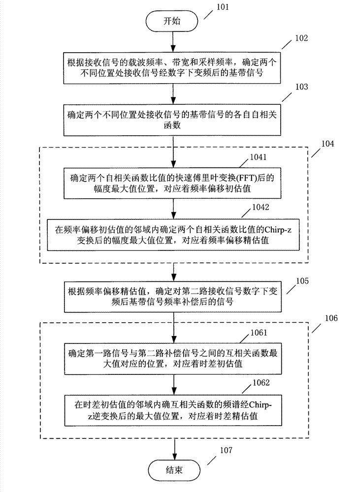
[0056] attached figure 1 Specific examples of the invention are given.

[0057] Key terms and symbol definitions in the embodiment:

[0058] x 1 (n) and x 2 (n) Baseband signals after digital down-conversion of received signals at two different locations

[0059] a 1 and a 2 Respectively represent the amplitude of the signal reaching two different positions

[0060] w 1 (t) and w 2 (t) variances are and The additive white noise of the two received signals of

[0061] f s Sampling frequency after digital down-conversion of the received signal

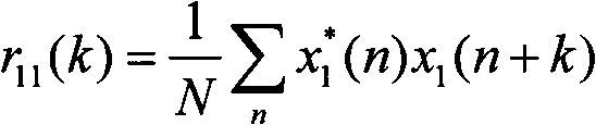
[0062] r 11 (k) and r 22 (k) Autocorrelation function of two baseband signals

[0063] x 1 (m) Fast Fourier Transform (FFT) of autocorrelation function ratio

[0064] m 1f Autocorrelation function ratio FFT transformation amplitude maximum position

[0065] f d0 Initial estimate of frequency offset

[0066] x 2 (m) at f d0 Chirp-z Transformation (CZT) of Autocorrelation Functi...


PUM


Abstract

The invention discloses a time difference measuring method for communication signals with frequency shift and belongs to the field of passive positioning of radiation sources. According to the characteristic that sequence of autocorrelation function ratios of received signals at two different positions is a single-harmonic function of frequency shift parameters, the two-dimensional parameter estimation problem of the frequency shift and time difference is changed into two one-dimensional parameter estimation problem. The time difference measuring method for communication signals with frequency shift includes determining baseband signals generated after digital down conversion of the received signals at the two different positions and respective autocorrelation functions of the baseband signals; obtaining initial frequency shift estimation value through Fourier conversion by the autocorrelation function ratios, and obtaining accurate estimation values by Chirp-Z conversion; determining frequency shift compensation to a second channel of baseband signals; and determining cross-correlation functions of a first channel of signals and a second channel of signals, looking for the maximum value to obtain initial time difference estimation value, and obtaining accurate estimation value of time difference to the cross-correlation functions by Chirp-Z conversion. The time difference measuring method can accurately quickly measure time difference for the communication signals with frequency shift and is widely applied to a signal passive positioning system of communication radiation sources.

Description

technical field [0001] The invention belongs to the field of radiation source passive positioning, relates to a time difference measurement technology, in particular to a communication signal time difference measurement method with frequency offset in a time difference positioning system. Background technique [0002] High-precision time difference measurement technology has important application value in the radiation source positioning of radar, sonar, satellite and communication systems. In a time-of-flight positioning system, any two receiving sensors are located at different positions in space, and receive signals from the same target radiation source in space after a certain propagation delay, and one of the received signals can be regarded as a time-delayed copy of the other received signal. The main idea of ​​the classic time difference of arrival (TDOA) measurement method is to shift the sampling sequence of one receiving signal relative to the sampling sequence of ...

Claims


Application Information

Patent Timeline
IPC IPC(8): H04W24/08H04W64/00
Inventor 魏合文叶尚福
Owner 中国人民解放军总参谋部第五十七研究所
Why Eureka
Try Eureka