
Optical laminate, polarizing plate, and display device

A technology of optical laminates and optical functional layers, applied in optics, identification devices, optical components, etc., can solve the problems of display image flashing, low density, and inability to alleviate the glare of LCD modules.

Active Publication Date: 2016-04-06
TOMOEGAWA PAPER CO LTD
View PDF4 Cites 0 Cited by
  • Summary
  • Abstract
  • Description
  • Claims
  • Application Information

AI Technical Summary

Problems solved by technology

[0008] Conventional optical laminates with high anti-glare properties have low density on the outermost surface, so glare of LCD modules cannot be alleviated, and display images flicker.

Method used


Image

  • Optical laminate, polarizing plate, and display device
  • Optical laminate, polarizing plate, and display device
  • Optical laminate, polarizing plate, and display device

Examples


Embodiment 1

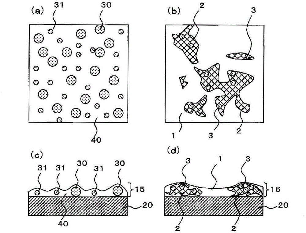
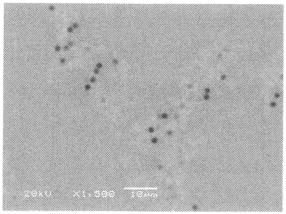
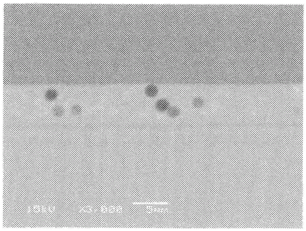
[0251] The paint for forming an optical functional layer obtained by stirring the predetermined mixture described in Table 1 with a disperser for 30 minutes was applied by roll coating (line speed: 20 m / min) to a film thickness of 60 μm and a total light transmittance of 92 % TAC (manufactured by Fuji Film Co., Ltd.; TD60UL) on one side of the transparent substrate, after pre-drying at 30-50°C for 20 seconds, drying at 100°C for 1 minute, and then irradiating ultraviolet rays (lamps) in a nitrogen atmosphere (nitrogen replacement) : Concentrating type high pressure mercury lamp, lamp output: 120W / cm, number of lamps: 4 lamps, irradiation distance: 20cm), thereby curing the coating film. Thereby, the optical laminated body of Example 1 which has an optical function layer with a thickness of 4.1 micrometers was obtained. From the results of SEM and EDS, it was confirmed that the optical functional layer constituting the obtained laminate had at least a first phase and a second p...

Embodiment 2

[0254] Except having changed the coating material for optical function layer formation into the predetermined liquid mixture described in Table 1, it carried out similarly to Example 1, and the optical laminated body of Example 2 which has the optical function layer of thickness 5.5 micrometers was obtained. From the results of SEM and EDS, it was confirmed that the optical functional layer constituting the obtained laminate had at least a first phase and a second phase, and formed a random aggregation structure.

[0255] (first invention, third invention)

Embodiment 3

[0257] Except having changed the coating material for optical function layer formation into the predetermined liquid mixture described in Table 1, it carried out similarly to Example 1, and the optical laminated body of Example 3 which has an optical function layer with a thickness of 5.5 micrometers was obtained. From the results of SEM and EDS, it was confirmed that the optical functional layer constituting the obtained laminate had at least a first phase and a second phase, and formed a random aggregation structure.

[0258] (first invention, third invention)


PUM

PropertyMeasurementUnit
particle sizeaaaaaaaaaa

Abstract

Disclosed are an optical laminate, a polarising plate and a display device with excellent production stability, which possess a good balance of excellent anti-glare properties and black colour display in bright areas combined with an anti-dazzle function. The optical laminate comprises an optical function layer layered on top of a translucent substrate, and is characterised in that: concave-convex shapes are formed in at least one surface of the optical function layer; the arithmetic mean height (Ra) of the optical function layer surface provided with the concave-convex shapes is equal to or greater than 0.040 and less than 0.200; and the distribution of angles of inclination in the optical function layer surface provided with the concave-convex shapes is such that the proportion of angles of 0.2 degrees or less in the distribution of angles of inclination is 30-95%.

Description

technical field [0001] The present invention relates to an optical laminate, a polarizing plate, and a display device. [0002] The optical laminated body of the present invention can be provided on the surface of a display such as a liquid crystal display (LCD), a plasma display (PDP), or an organic electroluminescence (OLED), or used as a constituent member of a display, or in order to improve the The light generated in the organic EL layer is extracted to the outside of the organic EL, so it is preferably used on the observation side. In particular, it relates to an optical laminate that emphasizes visibility such as anti-glare property, blackness in a bright room, and contrast in a dark room, and can be suitably used for displays such as televisions, for example. Background technique [0003] In liquid crystal display (LCD), plasma display (PDP) and other display devices, indoor lighting such as fluorescent lamps, sunlight incident from windows, shadows of operators, et...

Claims


Application Information

Patent Timeline
Patent Type & Authority Patents(China)
IPC IPC(8): G02B5/02B32B3/30B32B7/02G02B5/30G02F1/1335G09F9/00
CPCG02B5/0226G02B5/3033
Inventor 森内英辉中西隆之村田力
Owner TOMOEGAWA PAPER CO LTD
Learn More