Check patentability & draft patents in minutes with Patsnap Eureka AI!

Optocoupler structure, and optocoupler structure assembly method

An assembly method and optical coupling technology, applied in the coupling of optical waveguide, light guide, optics, etc., can solve the problems of complex assembly process and achieve the effect of simple assembly process

Active Publication Date: 2013-01-02
JAPAN AVIATION ELECTRONICS IND LTD
View PDF4 Cites 6 Cited by
  • Summary
  • Abstract
  • Description
  • Claims
  • Application Information

AI Technical Summary

Problems solved by technology

Therefore, the assembly process is complicated

Method used


Image

  • Optocoupler structure, and optocoupler structure assembly method
  • Optocoupler structure, and optocoupler structure assembly method
  • Optocoupler structure, and optocoupler structure assembly method

Examples


Embodiment 1

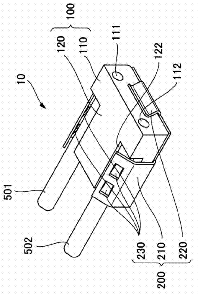
[0046] figure 2 It is a perspective view of the light coupling structure of Example 1, and FIG. 3 is a three-sided view of the light coupling structure of Example 1. FIG. Figure 3A for top view, Figure 3B for the front view, Figure 3C It is the left side view. Figure 4 yes Figure 3A The sectional view cut by the A-A line, Figure 5 yes Figure 3C A cross-sectional view taken along line BB. Figure 6 yes Figure 3A The cross-sectional view taken along the line CC is a view showing the state of optical coupling. Figure 7 Too Figure 3A The cross-sectional view taken along the line CC is a view showing another state of optical coupling.

[0047] The optical coupling configuration of Example 1 places the two optical fibers in physical contact with the lens. The optical coupling structure 10 is composed of a lens body 100 and a clamp 200 . The lens body 100 includes a lens portion 110 having lenses 111 , 112 and a fixing portion 120 . The lenses 111 and 112 shown...

Embodiment 2

[0065] Figure 13 It is a perspective view of the light coupling structure of Example 2, and FIG. 14 is a three-sided view of the light coupling structure of Example 2. FIG. Figure 14A is a top view, Figure 14B is the front view, Figure 14C It is the left side view. Figure 15 yes Figure 14A The sectional view cut by the D-D line, Figure 16 yes Figure 14C A cross-sectional view taken along line E-E.

[0066] The optical coupling configuration of Example 2 places the two optical fibers in physical contact with the lens. The optical coupling structure 70 is composed of a lens body 700 and a clamp 800 . The lens body 700 includes a lens portion 710 having lenses 711 , 712 and a fixing portion 720 . The structures, functions, etc. of the lenses 711 and 712 are the same as those of the lenses 111 and 112 of the first embodiment, and the optical characteristics can be appropriately designed according to the type of optical coupling to be performed.

[0067] The fixing...


PUM


Abstract

Disclosed is an optocoupler structure wherein force whereby an optical fiber end face is pressed upon a lens is sustained. The disclosed optocoupler structure is configured of a lens body and a clamp. The lens body comprises a lens unit, further comprising a lens, and an anchoring unit. The anchoring unit further comprises an optical fiber guide wherein the optical axis of an optical fiber is positioned when the optical fiber is imposed thereupon. The clamp further comprises a positioning unit, a pressure spring, and a retaining unit. The positioning unit positions the clamp, excluding the direction of the optical axis of the optical fiber. The pressure spring makes contact with the end face of the optical fiber and the face of the lens body that matches the direction of the normal, and generates recoil when the clamp moves in the opposite direction to the direction of the normal of the face of the lens. The retaining unit is formed in a component of the clamp that presses the optical fiber, and retains such that the optical fiber does not move in a direction away from the lens.

Description

technical field [0001] The present invention relates to an optical coupling configuration for optically coupling a lens and an optical fiber and a method of assembling the optical coupling configuration. Background technique [0002] As a technique for optically coupling a lens and an optical fiber, there is a method of using an adhesive. As one of such techniques, there is a technique described in Patent Document 1, for example. In the technique described in Patent Document 1, optical fibers are aligned using a pressure plate to a lens component (lens + guide groove), and fixed with an adhesive. In addition, FIG. 1 is FIG. 1 of Patent Document 1, Figure 1A is a perspective view of an optical coupler shown in Patent Document 1, Figure 1B It is a sectional view of the optical coupler shown in patent document 1. 1A is an optical coupler, 2A is a lens component, 3A is a lens forming part, 4A is a fiber holding part, 5A is a collimator lens, 6A is a fiber guide groove, 7 is...

Claims


Application Information

Patent Timeline
IPC IPC(8): G02B6/32G02B6/36
CPCG02B6/3636G02B6/322G02B6/4204G02B6/327Y10T29/49817G02B6/26G02B6/32
Inventor 蓝原周一
Owner JAPAN AVIATION ELECTRONICS IND LTD
Features
  • R&D
  • Intellectual Property
  • Life Sciences
  • Materials
  • Tech Scout
  • Unparalleled Data Quality
  • Higher Quality Content
  • 60% Fewer Hallucinations
Learn More