
Seaming mechanism of can manufacturing machinery

A seaming and mechanical technology, which is applied to other household appliances, household appliances, applications, etc., can solve the problems of large volume, inability to process seven-layer seaming procedures, and repeated components, so as to achieve high processing efficiency, reduce parts composition, and improve efficiency effect

Active Publication Date: 2013-01-09
新益机械工厂股份有限公司
View PDF11 Cites 1 Cited by
  • Summary
  • Abstract
  • Description
  • Claims
  • Application Information

AI Technical Summary

Problems solved by technology

[0004] The technical content disclosed in this new patent can achieve the good combination effect of making the tank body have seven layers of seaming. A single seaming die head and a single roller, but there are repeated components and resulting in excessive volume defects, especially when there is a processing requirement for high-speed seaming, these structures will not be able to perfectly achieve seven The processing procedure of layer seaming

Method used


Image

  • Seaming mechanism of can manufacturing machinery
  • Seaming mechanism of can manufacturing machinery
  • Seaming mechanism of can manufacturing machinery

Examples


Embodiment Construction

[0027] Hereinafter, a preferred embodiment of the present invention will be cited and further described with reference to the accompanying drawings.

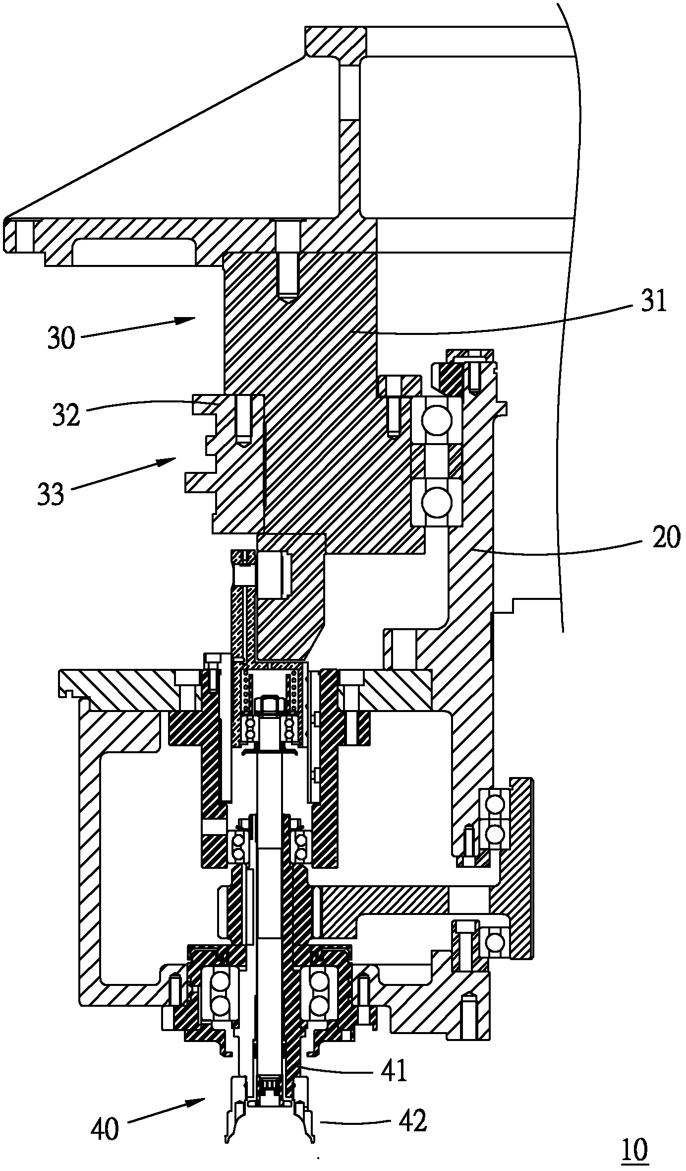
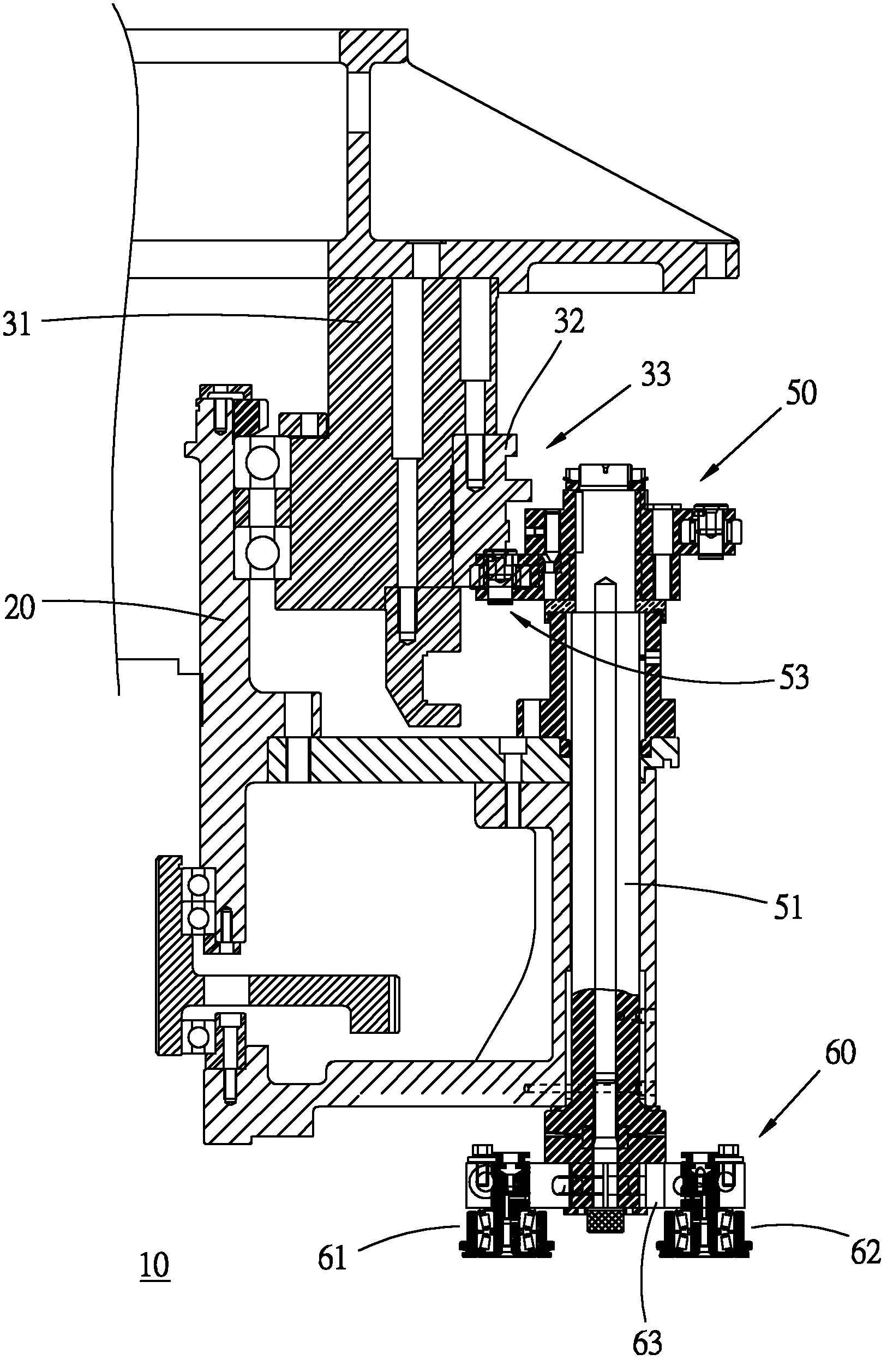
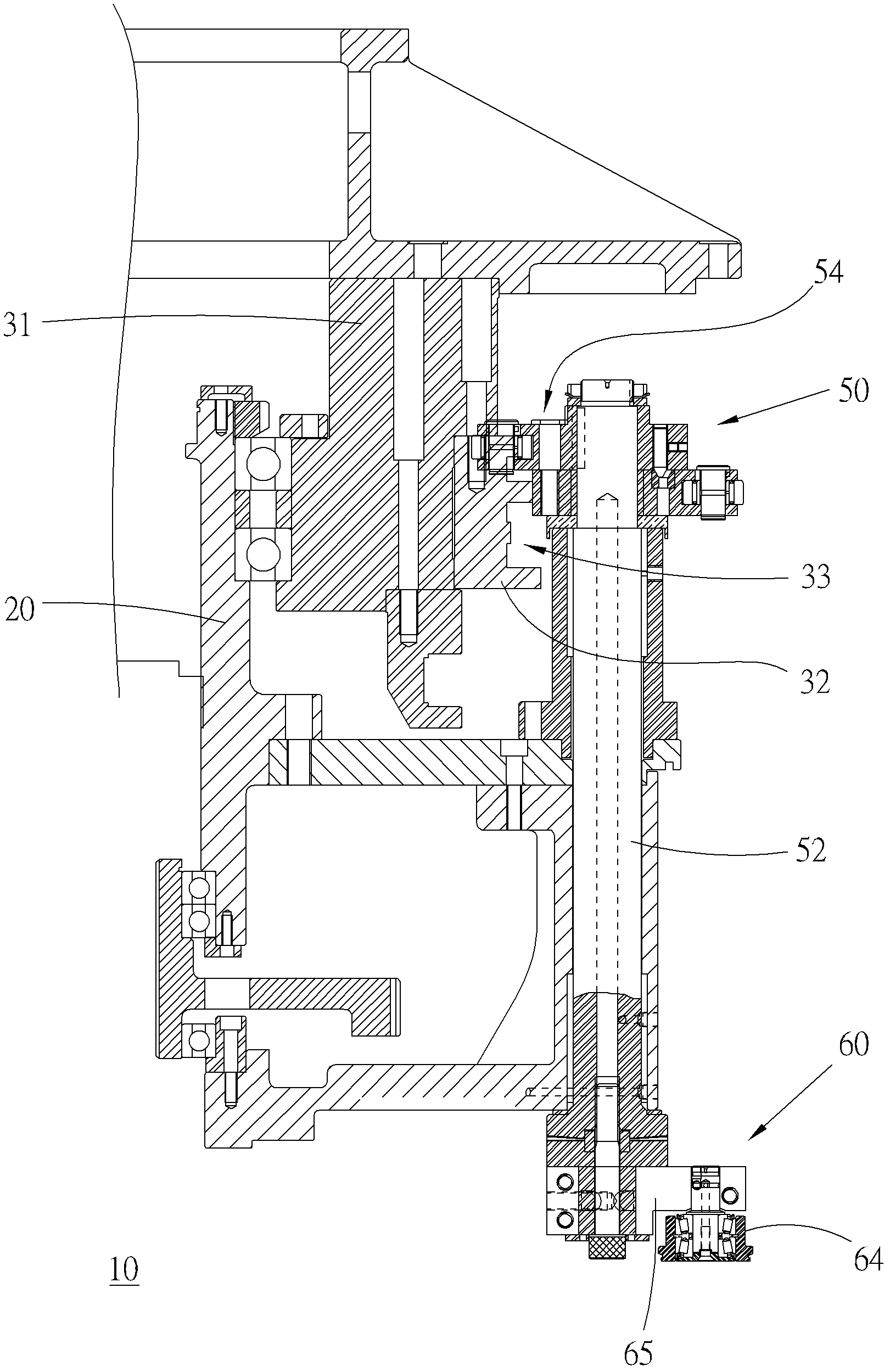
[0028] Please refer to shown in each figure, the seaming mechanism 10 of can making machine provided in a preferred embodiment of the present invention, it mainly consists of a main shaft 20, a guide 30, some rolling groups 40, some seaming shaft groups 50 And several seaming modules 60 are formed.

[0029] The main shaft 20 is in the shape of an upright tube for the guide member 30 to pivot on it, and each of the rolling group 40, the seaming shaft group 50 and the seaming module 60 are arranged equidistantly around the main shaft 20. Circumferential side, and can move around the axial direction of the main shaft 20 under the drive of external force.

[0030] The guide 30 has an annular body 31 coaxially pivoted on the top of the main shaft 20, an annular cam 32 coaxially fixed on the peripheral side of the body 31, and a plur...


PUM


Abstract

The invention discloses a seaming mechanism of can manufacturing machinery. The seaming mechanism of the can manufacturing machinery comprises a guide piece, a plurality of rolling groups, a plurality of seaming shaft groups and a plurality of seaming mold groups, wherein the guide piece is arranged on a main shaft, provided with an annular guiding part and around the periphery of the main shaft; The rolling groups are located at the periphery of the main shaft in same space and are respectively provided with rolling shafts and rolling heads arranged axial end of the rolling shaft; the plurality of seaming shaft groups are adjacent to the corresponding rolling shafts, wherein each seaming shaft group is provided with a first seaming shaft, a second seaming shaft, a first guided part and a second guided part, and respectively bridged between the axial end of each seaming shaft and the guiding part; and the plurality of seaming mold groups are respectively adjacent to the corresponding rolling heads, each seaming mold group is provided with a column-shaped first seaming mold head and a column-shaped third seaming mold head, a first seaming arm part, a column-shaped second seaming mold head, wherein the first column-shaped first seaming mold head and the column-shaped third seaming mold head are in parallel to the first seaming shafts around the column shaft and are adjacently corresponding to the rolling heads, the first seaming arm part is bridged and fixedly connected among the other axial ends of the first seaming mold head, the third seaming mold head and the first sealing shaft, the column-shaped second seaming mold head is in parallel to the second seaming shaft around the column shaft and is adjacently corresponding to the rolling heads, and the second seaming arm part is bridged and fixedly connected between the other axial ends of the second seaming mold head and the second seaming shaft.

Description

technical field [0001] The invention relates to can-making machinery, in particular to a rolling-sealing mechanism of the can-making machine. Background technique [0002] In the field of metal can making technology, usually the tubular can body and the bottom cover are first rolled and sealed into a cylindrical semi-finished product, and after filling the semi-finished product with appropriate content, the top cover is rolled and sealed on the cylindrical shape. The opening end of the semi-finished product is completed, and the seaming mechanism used to combine the lid body with the can body is generally constructed by winding the can body around the can body tube axis through the seam sealing die. On the peripheral side, the joint parts between the cover body and the can body are crimped sequentially to achieve the effect of sealing. [0003] Since the number of rolls between the tank body and the lid directly affects the compressive strength of the tank, there is a conve...

Claims


Application Information

Patent Timeline
Patent Type & Authority Applications(China)
IPC IPC(8): B21D51/32
Inventor 林秋金
Owner 新益机械工厂股份有限公司
Learn More