
Precision comparison and precision compensation method for ultra-precision manufacturing equipment based on bond length of graphene

A graphene and ultra-precision technology, which is applied in the field of sub-nanometer precision comparison and precision compensation of ultra-precision manufacturing equipment, can solve problems such as poor measurement stability, achieve good stability, and avoid secondary clamping errors.

Inactive Publication Date: 2013-01-09
XI AN JIAOTONG UNIV
View PDF4 Cites 0 Cited by
  • Summary
  • Abstract
  • Description
  • Claims
  • Application Information

AI Technical Summary

Problems solved by technology

[0003] Due to the influence of various conditions, the traditional detection method has poor measurement stability

Method used


Image

  • Precision comparison and precision compensation method for ultra-precision manufacturing equipment based on bond length of graphene
  • Precision comparison and precision compensation method for ultra-precision manufacturing equipment based on bond length of graphene
  • Precision comparison and precision compensation method for ultra-precision manufacturing equipment based on bond length of graphene

Examples


Embodiment Construction

[0017] The present invention will be further described in detail below in conjunction with the accompanying drawings. This method is implemented on the TECNAI20U-TWIN high-resolution transmission electron microscope of the Netherlands Philips (PHILIPS) company. The pattern generator used is DY2000A.

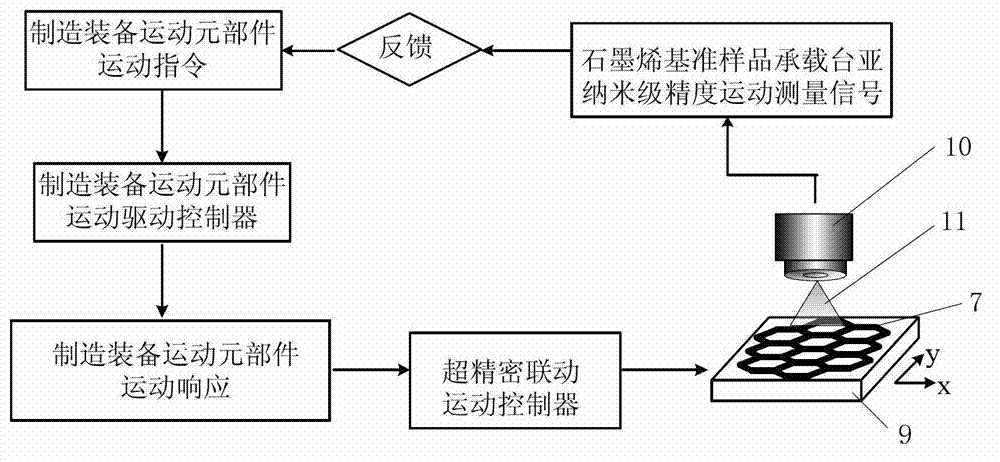
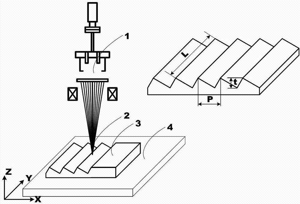
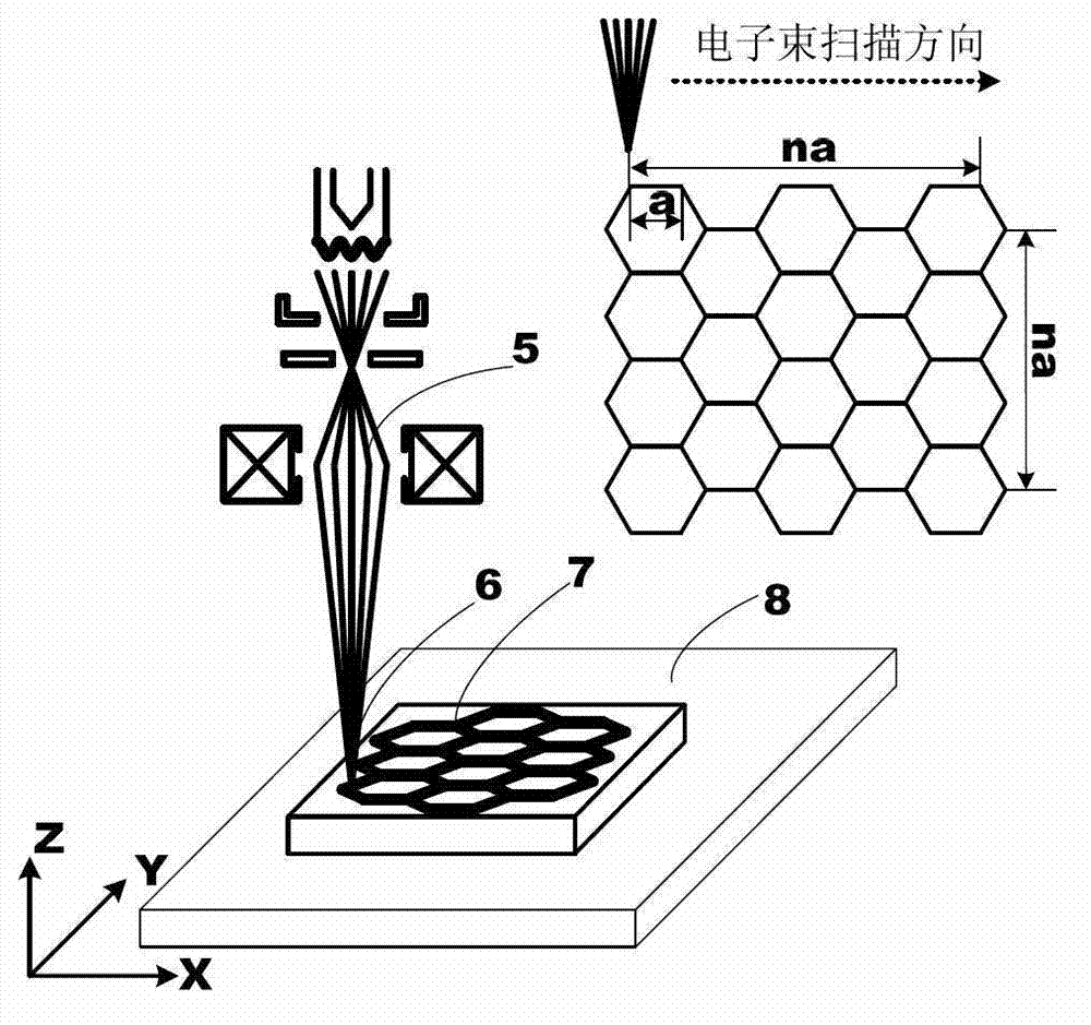
[0018] figure 1 It is a motion control and detection block diagram of the method of the present invention. figure 2 It is a schematic diagram of an ultra-precision machining device according to the method of the present invention (in this example, high-energy beam processing is taken as an example), wherein 1 is a high-energy beam emitting device, 2 is a high-energy beam spot, 3 is a workpiece, and 4 is a manufacturing equipment moving element Components (in this example, a moving platform); the processed feature structure includes groove depth t, period P, and groove length L. image 3 It is a schematic diagram of the detection device of the method of the present invention (...


PUM


Abstract

The invention discloses a precision comparison and precision compensation method for ultra-precision manufacturing equipment based on the bond length of graphene, which comprises the following steps of: carrying out ultra-precision linkage control connection on a motion component of the manufacturing equipment to be detected and a graphene reference sample bearing platform, characterizing the motion length of the graphene reference sample bearing platform through scanned bond length number of graphene, and carrying out real-time detection on the motion of the graphene reference sample bearing platform, thereby calculating the sub-nanometer-level precision motion length of the motion component of the manufacturing equipment; and feeding back a sub-nanometer-level precision detection signal to a motion control system of the motion component of the manufacturing equipment, comparing the signal with an expected motion length of the motion component of the manufacturing equipment, and carrying out motion length closed-loop control on the motion component of the manufacturing equipment, thereby realizing the sub-nanometer-level precision error compensation. According to the method disclosed by the invention, the sub-nanometer-level precision detection and sub-nanometer-level precision compensation of the motion component of the manufacturing equipment can be realized, and therefore, the method has a broad development prospect in the implementation field of nanometer / sub-nanometer-level precision nano manufacturing equipment.

Description

technical field [0001] The invention relates to a sub-nanometer precision comparison and precision compensation method for ultra-precision manufacturing equipment, which is used in the field of micro-nano manufacturing. Background technique [0002] Nano-manufacturing is a research hotspot in the world today. Nanofabrication is the core of nanomanufacturing, and nanometering is the main means of information collection and analysis in nanomanufacturing. The traditional micro-nano manufacturing method uses testing equipment to characterize geometric parameters such as surface morphology, roughness, and straightness after the sample is processed. The separation of processing and measurement processes makes the manufacturing accuracy poor and increases the secondary clamping error. Integrating nano-processing and nano-measurement to realize closed-loop control of the nano-processing process is the only way to improve the precision of nano-processing and realize nano / sub-nanomet...

Claims


Application Information

Patent Timeline
Patent Type & Authority Applications(China)
IPC IPC(8): B81C99/00
Inventor 刘红忠蒋维涛陈邦道丁玉成卢秉恒
Owner XI AN JIAOTONG UNIV
Learn More